Hello guys, welcome back to my blog. In this article, I will discuss what is clipper circuit, the types, the working of clipper circuits, the advantages, the disadvantages, the applications of clipper circuits, etc.
If you have any doubts related to electrical, electronics, and computer science, then ask question. You can also catch me @ Instagram – Chetan Shidling.
Also, read:
- What Is Interrupt, Interrupts Handling, Interrupt Service Routine
- What is Linear Integrated Circuits, Why It is Used, Working & Applications
- What Is FPGA, Field Programmable Gate Array, FPGA Tools
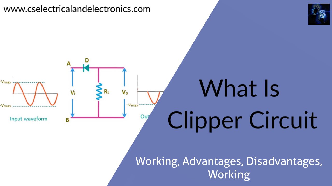
What Is Clipper Circuit
A clipper circuit prevents the output waveform from exceeding a certain level and at the same time, it does not distort the remaining part of the waveform. Clippers are networks that employ diodes to clip away a position of an input signal without distortion. Clipper Circuits are used in overvoltage protection circuits to prevent the circuits from high voltage spikes. Depending on the direction of the given rectifier diode, the positive or negative region of the input signal is clipped off.
Working Of Clipper Circuit
The Clipper circuits can be designed by using the diode and the resistors. We know that the simplest form of the Clipper Circuit is the half-wave rectifier, which can be designed just by using the diode and the resistor. Whenever the AC signal is applied to the given rectifier, then the signal passes through the positive half cycle, and then it rejects the negative half cycle of the rectifier.
By reversing the direction of the diode there is a possibility to pass the negative half cycle and then reject the positive half cycle. So, depending on one of the portions of the waveform is clipped, the Clipper circuit can be classified as either a positive Clipper circuit or a negative Clipper circuit. And further depending on the position of the diode, the Clipper Circuits are classified as either as a series Clipper Circuit or a parallel Clipper Circuit. So, in the case of the series Clipper Circuit, the diode is connected in series with the load resistor.
In parallel Clipper Circuit, the output is measured directly across the diode. In other words, we can say that the load is connected in parallel with the diode.
Parallel Clipper Circuit:-
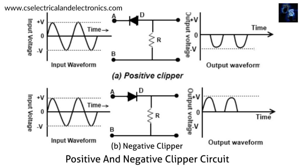
For simplicity, throughout the analysis, we will assume that the diode which is used is the ideal diode. So, now during the positive half cycle, this diode will get turned ON, or it acts as a short circuit. Always during the positive half cycle, the output of the circuit will be equal to zero. During the negative half-cycle, this diode will exactly act as a reverse bias. Simply the diode will act as an open circuit.
During the negative half-cycle, the output will follow the input voltage of the given circuit. Considering the ideal diode eliminates the positive half cycle and allows the negative half cycle. So, we can call it the positive Clipper circuit.
Similarly, we can design the negative Clipper circuit by reversing the direction of the diode. During the positive half cycle, the diode will act as an open circuit and the output will follow the input signal given by the diode. During the negative half cycle of the rectifier, this diode will get turned ON. So, it will act as a short circuit and during the negative half cycle, the output of the circuit will be equal to zero.
Clipper Circuit with Biasing voltage:-
For analysis, purposes draw a reference line that represents the voltage of V volt. Now, this diode of the Clipping circuit will get turned ON, whenever the input voltage Vin is greater than V volt. Whenever the input voltage is less than V volt, then this diode will act as an open circuit.
Clipper Circuit with Zener diode:-
Instead of using the two biasing voltages in the circuit, the same waveform can also be achieved by using the back-to-back Zener diodes of the Clipper Circuit. The Zener voltages of the diodes D1 and D2 are V1 and V2 respectively. By using this circuit it is possible to achieve the same waveform.
Series Clipper_Circuit:
The simplest form of series Clipper Circuit is the half-wave rectifier. If we consider an actual diode, then this actual diode will conduct whenever the input voltage of the diode Vin is greater than 0.7V. In the above case, the peak amplitude of the output waveform of this circuit will be equal to Vm-0.7V. By reversing the direction of the diode, there is a possibility to eliminate the positive half cycle and can pass the negative half cycle.
Series Clipper_Circuit with Biasing voltage:-
In this Circuit, the diode will conduct whenever the input voltage (Vin-V) volt is greater than zero. Just for analysis draw a reference voltage. So, when the input voltage of the diode Vin is less than V volt, during this time the diode will act as reverse bias and it will act as an open circuit. During this time, the output voltage of the diode Vout will be equal to zero. When the input voltage is less than V volt then during this time, the output will be equal to zero.
Whenever the input voltage goes above the V volt, then this diode starts conducting. At this time, the output voltage across the load resistor will be equal to Vin-V volt. The peak amplitude of the signal will be equal to Vm-V volt. Similarly, for the negative half cycle, the diode will still remain the reverse bias. For the negative half cycle, the output voltage Vout will be equal to zero.
Advantages of clipper circuit:-
Clipping circuits serve as overvoltage protection for sensitive devices.
Disadvantages of clipper circuit:-
01. The data transmitted at values outside the range of the circuit will be clipped as the signal transmission is considered.
02. In high-frequency signals transmission occurs through the diode capacitance which is undesirable.
Applications of clipper circuit:-
01. Clipper Circuits are used to alter the shape of a waveform and to provide circuit transient protection.
02. Clipper Circuits are used for generating new waveforms.
03. These circuits are frequently used in FM Transmitters for removing the excess ripples in the signals above a certain noise level.
04. Clipper Circuits are also used in power supplies.
I hope this article may help you all a lot. Thank you for reading.
Also, read:
- 10 Free ADAS Projects With Source Code And Documentation – Learn & Build Today
- 100 + Electrical Engineering Projects For Students, Engineers
- 100+ Indian Startups & What They Are Building
- 1000+ Automotive Interview Questions With Answers
- 1000+ Electronics Projects For Engineers, Diploma, MTech Students
- 1000+ MATLAB Simulink Projects For MTech, Engineering Students
- 2000+ Embedded Systems Interview Question Bank
- 2026 Hackathons That Can Change Your Tech Career Forever