
Hello guys, welcome back to our blog. Here in this article, we will discuss what is single line diagram in a substation, various symbols used in single-line diagrams to represent components, and what is the purpose of a single-line diagram.
If you have any electrical, electronics, and computer science doubts, then ask questions. You can also catch us on Instagram – CS Electrical & Electronics.
Also, read:
- Top 20 Reasons Why Gravel Or Stones Are Used In Substations
- Top 10 Electronic Starters Used In Electrical Motors, Latest Starters
- Top 20 Algorithms Electrical And Electronics Engineers Must Know
Single Line Diagram In Substation
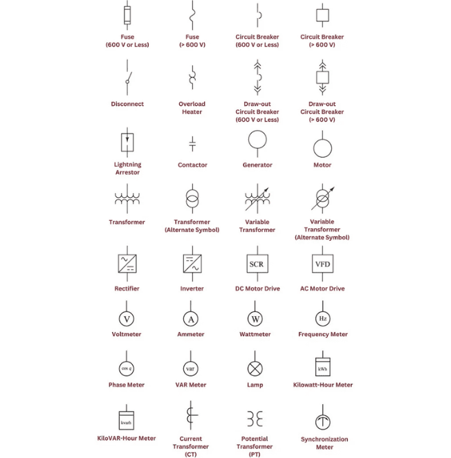
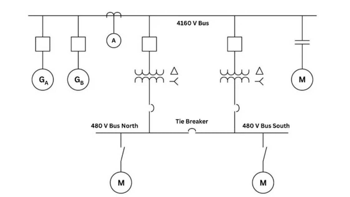
A simplified graphical representation of a substation’s electrical power system is called a single-line diagram (SLD). The key parts and connections of the substation, such as transformers, circuit breakers, disconnect switches, busbars, and other equipment, are depicted on a single-line drawing.
Engineers and technicians utilize the SLD to comprehend, examine, design, and troubleshoot the electrical power system. In addition to showing the system’s power flow and current direction, it also gives a visual overview of the substation’s layout, electrical connections, and equipment.
A single-line diagram (SLD) is a condensed graphical representation of a substation’s electrical power system. Transformers, circuit breakers, disconnect switches, busbars, and other equipment are all depicted on a single-line design that depicts the essential parts and connections of the substation.
Engineers and technicians may comprehend, evaluate, design, and troubleshoot the electrical power system using the SLD. It shows the layout, electrical connections, and equipment of the substation as well as the direction and flow of current as well as the flow of electrical power.
The lines that connect the parts signify the electrical connections and demonstrate the movement of electrical power. The kind and thickness of the lines in the diagram serve as indicators of the voltage and power of the equipment they represent.
Substation systems are designed, planned, and run using single-line diagrams. They aid engineers and technicians in performance analysis, the detection of possible issues, and the planning of system improvements or upgrades. Single-line diagrams are a helpful teaching tool for new employees and for explaining the setup and operation of the substation to others.
CAD software or specialized substation design software is generally used to construct single-line diagrams. Using standardized symbols and lines, the program enables the engineer to quickly and correctly build and alter the diagram.
A single-line diagram may also provide extra information in addition to the primary connections and components of the substation, like:
- Protection and control systems: This includes relays, switches, and other equipment used to protect the substation and connected power systems from faults and overloads.
- Metering and monitoring equipment: This includes devices used to measure and monitor electrical parameters such as voltage, current, and power factor.
- Communication systems: This includes equipment used to transmit data between the substation and other parts of the power system, such as a control center or other substations.
- Auxiliary systems: This includes equipment such as batteries, chargers, and ventilation systems, which are necessary for the safe and reliable operation of the substation.
In general, a single-line diagram offers a clear and orderly representation of an electrical system at a substation. It aids engineers and technicians in comprehending the layout of the system, seeing potential problems, and selecting appropriate options for design, upkeep, and operation.
Single-line diagrams are an essential tool for designing and operating substation systems. Here are some additional aspects to consider:
- System protection: Single-line diagrams help engineers design protection schemes for the substation system. The diagram shows the locations of protection devices and the direction of the protection signals, which enables engineers to ensure that the protection scheme is properly coordinated.
- System planning: Single-line diagrams are used to plan modifications and upgrades to the substation system. Engineers can use the diagram to evaluate the impact of adding or removing equipment, or changing the system configuration.
- Safety considerations: Single-line diagrams provide important safety information, such as the locations of grounding points and the voltage levels at different points in the system. This information is critical for ensuring that workers can safely operate and maintain the substation.
- Troubleshooting: Single-line diagrams can help technicians to troubleshoot problems in the substation. By tracing the flow of power through the system, technicians can identify the location of faults and determine the appropriate corrective action.
In summary, a single-line diagram is a simplified graphical representation of a substation’s electrical system. It is an important tool for designing, operating and maintaining the substation, and it provides a concise and organized way to communicate information about the system to engineers, technicians, and other stakeholders.
This is about “Single Line Diagram In Substation“. I hope this article may help you all a lot. Thanks for reading.
Also, read:
- 10 Tips To Maintain Battery For Long Life, Battery Maintainance
- 10 Tips To Save Electricity Bills, Save Money By Saving Electricity
- 100 (AI) Artificial Intelligence Applications In The Automotive Industry
- 100 + Electrical Engineering Projects For Students, Engineers
- 100+ Indian Startups & What They Are Building
- 1000+ Automotive Interview Questions With Answers
- 1000+ MATLAB Simulink Projects For MTech, Engineering Students
- 2024 Is About To End, Let’s Recall Electric Vehicles Launched In 2024