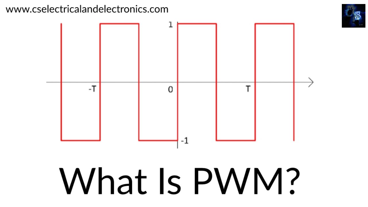
Different Types Of PWM Techniques, Pulse Width Modulation
Hello guys, welcome back to my blog. In this article, I will discuss different types of PWM techniques, pulse width modulation techniques, different methods of PWM, applications of pulse width modulation, etc.
If you have any doubts related to electrical, electronics, and computer science, then ask question. You can also catch me @ Instagram – Chetan Shidling.
Also, read:
- 200+ Electric Vehicle Projects For Engineers, MTech, Ph.D., Diploma.
- Difference Between PI, PID, Fuzzy Logic Controller, Disadvantages.
- 500+ Matlab Simulink Projects Ideas For Engineers, MTech, Diploma.
Different Types Of PWM Techniques
To reduce the average power delivered by an electrical signal by making it into different parts (chopping). By switching the supply, the average voltage fed to the load is controlled. We can vary the pulse width by turning on and turning off the different switches of the inverter. The pulse width modulation is used to control the analog devices.
Because of its high efficiency, low power loss, and its ability to control power, this technique is used in many applications. This PWM is extensively used in power electronic applications. We can control the brightness of the LED circuit and also can control the speed of the DC motors. Two factors are always associated with it one is the switching frequency and the second is the duty cycle.
If the switching frequency is 1Hz, there is flickering in the LED. But instead of 1Hz, if the switching frequency is 500Hz, then the switch will get turned ON or OFF very rapidly. In this case, the LED is continuously in the ON condition.
Duty Cycle:-
The ratio of the ON time to the total time period is known as the duty cycle. So, for some waveform, if the duty cycle is 50 percent that means the pulse remains ON for 50 percent of the time.
PWM Techniques
01. Single pulse width modulation technique:-
Used for single-phase circuits. Changing the width of the pulse to control the on-time or to control the gate signal of a transistor so that the output voltage of the inverter can be controlled. By changing the width or by changing the width of the courier signal we can definitely change the on-time of the transistor. As we vary the time of the transistor we can vary the inverter output voltage. So, if the width of the gate pulse that we are getting as an output or comparator after pulse width modulation is the width of the output voltage will be getting is d.
02. Third harmonic injection pulse width modulation:-
The third harmonic voltage is not present on the phase voltages and the line to line for a three-phase load with a neutral point which is of floating-point type. Hence, it does not causes any distortion on the phase voltages. By adding a third harmonic signal in a low-frequency sinusoidal reference signal, we can get the amplitude increase in output voltage waveform.
03. Multiple pulse width modulation:-
Multiple pulse width modulation consists of multiple numbers of pulses per half cycle of the output voltage. Each pulse can be varied by the carrier signal. The frequency of the triangular wave is greater than that used in single pulse width modulation and it decides the number of gating signals per half cycle. By using multiple pulses, the harmonic content can be reduced. The frequency decides the number of pulses per half cycle. The output voltage can be controlled by controlling the modulation index.
04. Sinusoidal pulse width modulation:-
It indicates that the generation of outputs of the pulse width modulation with a sine wave as the modulating signal. The switching time of a PWM signal can be obtained by comparing a reference sinusoidal wave with a triangular wave of high frequency. This type of pulse width modulation is widely used in industrial applications. The RMS value of the output voltage can be varied by varying the modulation index. This technique improves the distortion factor and eliminates all harmonics less than or equal to 2p-1. By using a filter we can easily remove the higher-order harmonics.
05. Hysteresis band pulse width modulation:-
In this technique, the output is free to oscillate within the predefined error band known as the hysteresis band. The switching frequency of power devices is not fixed constantly and will change depending upon the magnitude and frequency of the reference signal. The main benefit of this control scheme is its ability to respond rapidly to load and line transients.
06. Space vector pulse width modulation:-
Space vector PW modulation (SVPWM) is an algorithm for the control of pulse width modulation (PWM). It is employed for the creation of alternating current (AC) waveforms, it is most commonly to drive 3 phase AC powered motors at varying speeds from DC using multiple class-D amplifiers. The harmonic present at the output is decreased and Hence this vector modulation method offers an optimal output current or voltage.
I hope this article “Different Types Of PWM Techniques” may help you all a lot. Thank you for reading.
Also, read:
- 10 Tips To Maintain Battery For Long Life, Battery Maintainance
- 10 Tips To Save Electricity Bills, Save Money By Saving Electricity
- 100 (AI) Artificial Intelligence Applications In The Automotive Industry
- 100 + Electrical Engineering Projects For Students, Engineers
- 1000+ Control System Quiz, Top MCQ On Control System
- 1000+ Electrical Machines Quiz, Top MCQs On Electrical Machines
- 1000+ MATLAB Simulink Projects For MTech, Engineering Students
- 2024 Is About To End, Let’s Recall Electric Vehicles Launched In 2024

