
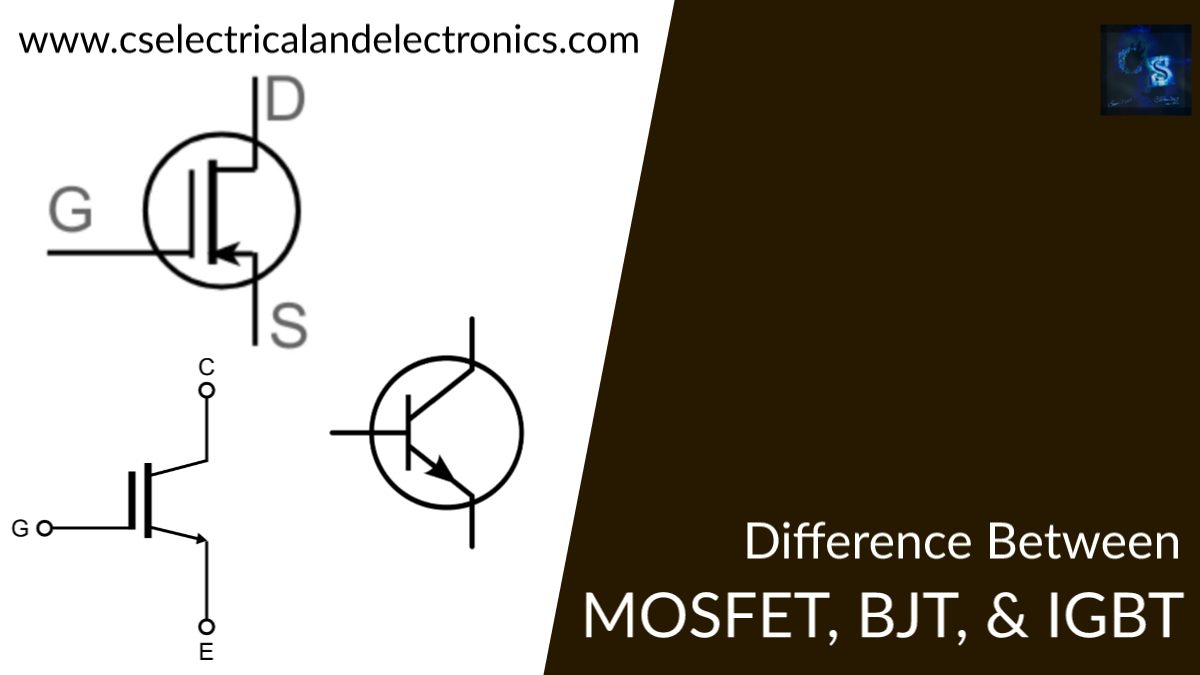
Difference Between MOSFET, BJT, and IGBT
Hello guys, welcome back to my blog. In this article, I will discuss the difference between MOSFET, BJT, and IGBT, what is MOSFET, what is BJT, and what is IGBT,
If you have any electrical, electronics, and computer science doubts, then ask questions. You can also catch me on Instagram – CS Electrical & Electronics And Chetan Shidling.
Also read:
- Difference Between Transmission And Distribution Lines
- Difference Between 2G, 3G, 4G, 5G Technology, Benefits, Drawbacks
- Difference Between Cascaded H-Bridge, Flying capacitors, Diode Clamped multilevel inverter
Difference Between MOSFET, BJT, and IGBT
Transistors play a crucial role in modern electronics. The Metal-Oxide-Semiconductor Field-Effect Transistor (MOSFET), Bipolar Junction Transistor (BJT), and Insulated Gate Bipolar Transistor (IGBT) are three commonly used types of transistors. Each has distinct properties and applications.
In this guide, we will explore the fundamental differences between MOSFET, BJT, and IGBT in terms of their working principles, structure, advantages, disadvantages, applications, and a detailed comparison.
Mosfet ( Metal oxide semiconductor field-effect transistors)
MOSFET stands for metal oxide semiconductor field-effect transistors. This is one of the types of field-effect transistors. The MOSFETs are very small that’s why this can be used to design VLSI Circuits with high density. MOSFET doesn’t contain a PN junction structure, instead of this, the gate of the MOSFET will be insulated by a silicon dioxide layer, Due to which the input resistance of MOSFET will be very high. MOSFET is also called IGFET because of the insulated gate terminal.
MOSFET carries the majority of charged particles. The switching frequency of the MOSFET will be too high. This MOSFET is suitable for low-power applications.
Structure:
- Consists of three layers: Emitter (E), Base (B), and Collector (C).
- Two types: NPN and PNP transistors.
- Works based on current flow between the collector and emitter, controlled by the base current.
Working Principle:
- A small current at the base controls a larger current flow between the collector and emitter.
- Modes of operation: Cut-off, Active, and Saturation.
Advantages:
✔ High current gain
✔ Good performance in analog circuits (amplifiers)
✔ Suitable for low-frequency applications
Disadvantages:
✖ High power dissipation
✖ Slow switching speed compared to MOSFET
✖ Requires continuous base current
Applications: Used in audio amplifiers, signal processing, analog circuits, and low-power switching.
BJT (Bipolar junction transistor)
BJT stands for bipolar junction transistor. It can be also called a solid-state current control device that can be used to switch a circuit. BJT is a 3 terminal device that contains an emitter, collector, and base. The current that will be flowing through the emitter and collector is controlled by the current flowing through the base.
BJT is a PNP transistor, which means it has two P-type regions and one N-type region. Similarly, in the case of NPN, where it has 2 N-type regions and one P-region. This BJT can be connected in three various configurations. Those are CB configuration, CE configuration, and CC configuration.
Structure:
- Has three terminals: Gate (G), Drain (D), and Source (S).
- Two types: N-channel and P-channel.
- Enhancement mode and depletion mode variants.
Working Principle:
- A voltage applied to the gate creates an electric field, controlling the current flow between drain and the source.
- The gate is insulated from the channel, making it a high-impedance device.
Advantages:
✔ Fast switching speed
✔ Low power consumption
✔ High efficiency in low-voltage applications
Disadvantages:
✖ Sensitive to electrostatic discharge (ESD)
✖ High on-state resistance compared to IGBT
Applications: Used in switching power supplies, RF circuits, and microprocessors.
IGBT (Insulated gate bipolar transistor)
It is a Fusion between BJT and MOSFET. IGBT stands for an insulated gate bipolar transistor. The IGBT Is a 3 terminal power semiconductor device that will be used as an electronic switch since it is a fast switching device. This contains 4 layers( P-N-P-N) which are controlled by a metal oxide semiconductor gate structure. It will be having high input impedance and low output impedance and the cost of IGBT will be high. IGBTs are most widely used in amplifiers for switching purposes.
Structure:
- Has three terminals: Gate (G), Collector (C), and Emitter (E).
- Combines MOSFET’s gate control with BJT’s conduction mechanism.
Working Principle:
- A voltage applied to the gate controls the current flow between collector and emitter.
- Offers low conduction losses like BJTs but retains fast switching speeds.
Advantages:
✔ High efficiency for high-voltage applications
✔ Low conduction loss
✔ Handles high currents efficiently
Disadvantages:
✖ Slower switching speed compared to MOSFET
✖ More expensive than MOSFETs and BJTs
Applications: Used in motor drives, industrial inverters, UPS systems, and high-power switching circuits.
Difference Between BJT, MOSFET, And IGBT
BJT
- ➢ The voltage rating is high but less than 1kv
- ➢ BJT is having low input impedance.
- ➢ Having a high output impedance.
- ➢ It’s having a slow switch speed.
- ➢ The cost of a BJT is low.
- ➢ It will be controlled by the base.
- ➢ It is a currently controlled device.
- ➢ It has a negative temperature coefficient.
- ➢ This BJT will be suitable for high-power applications.
- ➢ In BJT losses are low.
MOSFET
- ➢ The voltage rating is high, but less than 1kv.
- ➢ MOSFET has high input impedance.
- ➢ It has medium output impedance.
- ➢ The switching speed is fast.
- ➢ The cost of a MOSFET is medium.
- ➢ It will be controlled by the gate.
- ➢ It is a voltage-controlled device.
- ➢ Having a positive temperature coefficient.
- ➢ MOSFET will be suitable for low-power applications.
- ➢ In MOSFET losses are high.
IGBT
- ➢ The voltage rating is very high which is greater than 1kv.
- ➢ IGBT has high input impedance.
- ➢ Having low output impedance.
- ➢ The switching speed in IGBT is high.
- ➢ The cost of the IGBT is very high.
- ➢ It will be controlled by GATE.
- ➢ It is a voltage-controlled device.
- ➢ Has a negative temperature coefficient.
- ➢ Losses are less in IGBT.
Which One Should You Use?
Choosing between MOSFET, BJT, and IGBT depends on your application:
- Use MOSFET when you need high-speed switching and efficiency in low-to-medium power applications (e.g., SMPS, microcontrollers, RF circuits).
- Use BJT for analog signal processing, amplification, and low-frequency applications.
- Use IGBT when dealing with high-power and high-voltage applications, such as motor drives, industrial automation, and renewable energy systems.
Conclusion
MOSFET, BJT, and IGBT each serve different purposes in electronics and power applications.
- BJTs are ideal for amplification and low-power applications but suffer from slow speed and high power loss.
- MOSFETs excel in high-speed, low-power switching applications.
- IGBTs are the best choice for high-power applications, balancing efficiency and power handling
I hope this article may help you all a lot. Thank you for reading.
Also read:
- Difference Between Domain And Zonal Architecture in Automotive: A Complete Guide
- Roadmap To Become A Successful Hardware-in-the-Loop (HiL) Engineer
- 1000+ Automotive Interview Questions With Answers
- RTOS In The Automotive Industry: The Brains Behind Real-Time Vehicle Control
- High Performance Computers in Software-Defined Vehicles (SDVs): Architecture, Challenges, and Future Trends
- Automotive HPC Wars: The Race To Power Software-Defined Vehicles
- Why The Automotive Industry Is Down: No Automotive Jobs and When Will It Become Normal Again?
- Lane Departure Warning Systems: Your Guardian on the Road