
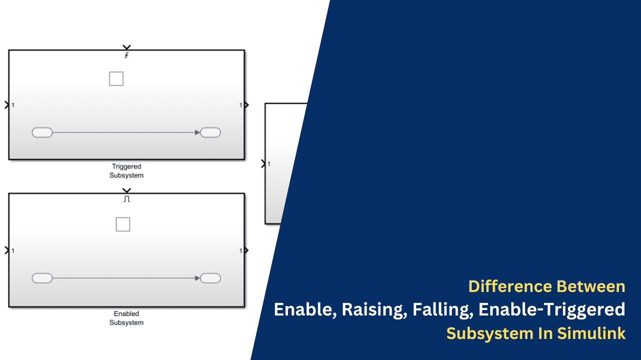
Difference Between Enable, Raising, Falling, Enable-Triggered Subsystem In Simulink
Hello guys. welcome back to our blog. Here in this article, we will discuss the difference between enable and trigger subsystems in Simulink and its applications.
Ask questions if you have any electrical, electronics, or computer science doubts. You can also catch me on Instagram – CS Electrical & Electronics.
- Top 20 MiL, SiL, MBD Bosch Interview Questions
- Artificial Intelligence-Based Electrical Machines & Drives
- What Is PTO In Vehicle, Power Take-Off, Working
Difference Between Enable, Raising, Falling, Enable-Triggered Subsystem In Simulink
Subsystems are fundamental Simulink building pieces that help divide large, complicated models into smaller, more manageable chunks, which makes the design and debugging processes easier. The subsystems labeled “Enable,” “Raising,” “Falling,” and “Enable-Triggered” provide distinct methods for regulating the conditions under which particular model components become active. The “Enable” subsystem facilitates dynamic activation based on simulation inputs by limiting the execution of its internal logic to positive control signals. This feature helps to maximize efficiency and resource utilization in situations where specific calculations or actions must be performed conditionally.
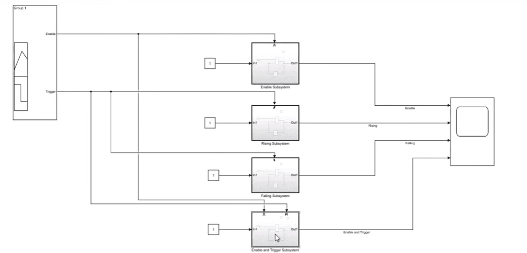
The “Raising” and “Falling” subsystems react to modifications in the condition of the control signal. When a control signal changes from a low to a high state, a “Raising” subsystem gets activated, and when it changes from a high to a low state, a “Falling” subsystem gets activated. Subsystems of this kind are essential for modeling events that rely on certain signal transitions, like determining when a process begins or ends. The “Enable-Triggered” subsystem executes its contents in response to a combination of enabling conditions and signal transitions, combining the capabilities of both enable and trigger methods. For applications needing exact control over simulation execution, this combination offers a potent tool for building intelligent and responsive models.
01. Enable Subsystem In Simulink
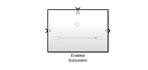
In Simulink, an “Enable Subsystem” is a particular kind of subsystem that only runs the blocks it contains when a particular enabling condition is satisfied. This feature optimizes performance and computational efficiency by preventing pointless calculations and enables the selective execution of specific portions of a model depending on a control signal.
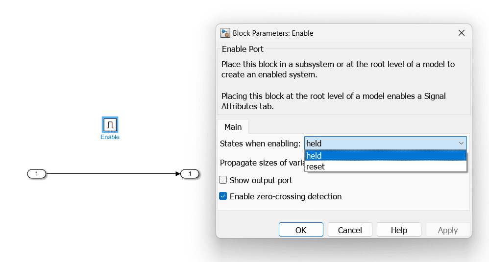
Enable Port: The control signal that determines whether the subsystem should be active enters through the enable port. Only when there is a positive (non-zero) signal at this port does the subsystem start up.
Held: An enabled subsystem maintains its internal states across cycles of enable and disable when the “held” option is chosen. Accordingly, upon re-enabling the subsystem, its functions carry on from the previous condition that it was in before its disabling.
Reset: An enabled subsystem that has the “reset” option chosen will always revert back to its original internal state when it is activated again. This implies that the subsystem begins anew each time it is enabled, just like it would be initializing.
Execution Control: The subsystem activates and its blocks run at each simulation time step when the enable signal is affirmative. The subsystem remains inactive and its blocks do not execute if the enable signal is zero or negative, hence preventing the subsystem from performing any calculations.
State Management: Allow for continuous state evolution throughout several simulation steps by enabling subsystems to maintain their internal states in between activations. Alternatively, contingent upon the configuration settings, they may have to reset their statuses every time they are enabled.
Initialization: Upon the first activation, a subsystem that has been enabled may have its blocks initialized. When starting conditions or parameters need to be set up again every time the subsystem is enabled, this capability comes in handy.
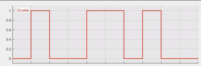
Input using Signal Builder:
Output of Enable Subsystem:
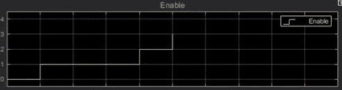
An Enabled Subsystem executes when an external control signal, known as the enable signal, is true (non-zero). When the enable signal is false (zero), the subsystem does not execute.
Key points about Enabled Subsystems are:
👉 Execution: When the enable signal is true.
👉 Initialization: The subsystem can be configured to hold or reset states when disabled.
👉 Usage: Useful when you want a subsystem to run conditionally based on some criteria.
Applications Of Enable Subsystem
a. Conditional Processing: To implement conditional logic, wherein specified computations or actions are carried out only in certain situations, enable subsystems are a perfect choice. They can be used, for instance, to simulate systems that switch between modes of operation in response to outside inputs.
b. Resource Optimisation: Enable subsystems to help lower computational load and increase simulation efficiency by only running when necessary. This is especially helpful in large and complicated models where not every component needs to be active at all times.
c. Control Systems: Enable subsystems in control systems that can simulate controllers that only come on when specific criteria are satisfied like a threshold being crossed or an event happening.
02. Triggered Subsystem in Simulink
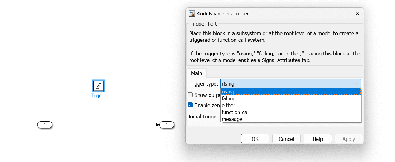
2.1. Rising Edge Triggered Subsystem
A unique kind of triggered subsystem in Simulink is called a Rising Edge Triggered Subsystem. It only starts executing its internal logic when the control signal changes from a low value, which is usually zero, to a high value, which is non-zero. This makes the subsystem perfect for event-driven modeling since it enables it to react to particular occurrences or situations indicated by the rising edge of the control signal.
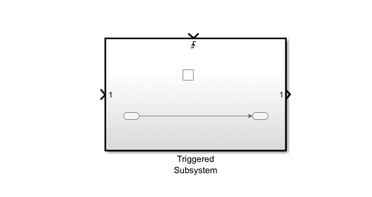
Trigger Port: The control signal that determines when the subsystem should operate enters through this port. The subsystem only operates when the signal is rising, which means it starts working when the signal swings from a low to a high value.
Execution Control: Initiated by the Rising Edge When the subsystem detects a rising edge, its contents are executed exactly once. The subsystem doesn’t run again if the control signal stays high or returns to low without a rising edge.
State Management: During the rising edge trigger event, the subsystem’s internal states can be set to be held or reset. Depending on the particular requirements of the application, this behavior can be changed.
Event-Driven Processing: This subsystem can be used to simulate systems that need to be precisely timed and handled, including digital circuits, communication protocols, and control systems, because it is made to act in reaction to certain events.
Input using Signal Builder:
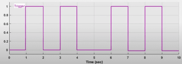
Output of Rising Edge Triggered Subsystem:
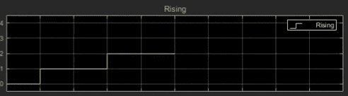
A Rising Edge Triggered Subsystem executes when the trigger signal changes from false (zero) to true (non-zero).
Key points include:
👉 Execution: On a rising edge of the trigger signal.
👉 Initialization: The subsystem can initialize states on the first trigger.
👉 Usage: Suitable for operations that need to occur when an event starts.
Applications Of Rising Edge Triggered Subsystem
a. Digital signal processing is necessary for devices like flip-flops, counters, and debouncing circuits that require operations to be performed in response to changes in input signals.
b. Events-Driven Systems: Perfect for applications like data recording, interrupt handling, or state transitions in state machines where specified actions must be taken at particular times.
c. Control Systems: Helpful in enabling prompt responses to changes in system states by initiating actions based on sensor inputs or control signals.
2.2. Falling Edge Triggered Subsystem
A specific kind of triggered subsystem in Simulink is called a Falling Edge Triggered Subsystem. It only functions internally when the control signal changes from a high value, which is usually non-zero, to a low value, which is zero. This makes the subsystem ideal for event-driven modeling, where actions must be triggered on signal drops, as it enables the subsystem to react to specific events indicated by the falling edge of the control signal.
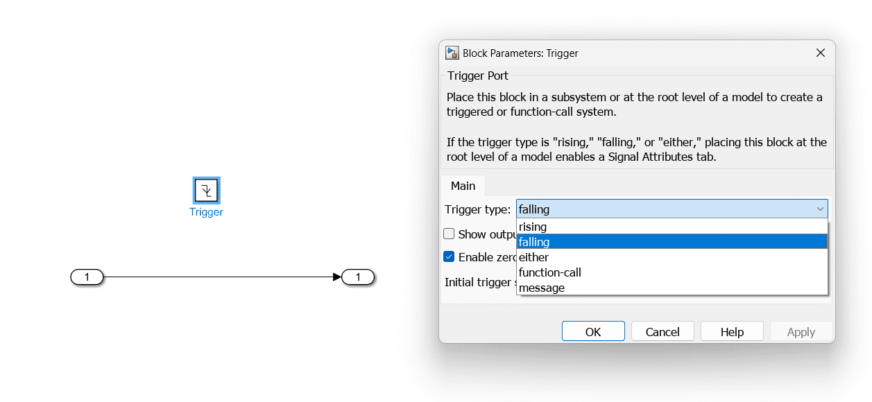
Trigger Port: The control signal that determines when the subsystem should operate enters through this port. The subsystem only operates while the signal is falling, that is when it transitions from a high value to a low value.
Execution Control: The Edge That Dropped When the subsystem detects a falling edge, its contents are executed exactly once. The subsystem doesn’t run again if the control signal stays low or changes back to high without a falling edge.
State Management: During the falling edge trigger event, the subsystem’s internal states can be adjusted to be held or reset. Depending on the particular requirements of the application, this behavior can be changed.
Event-Driven Processing: This subsystem is ideal for simulating systems that need exact timing and event handling, such as digital circuits, communication protocols, and control systems, because it is made to act in reaction to particular events.
Input using Signal Builder:
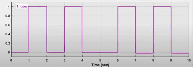
Output of Falling Edge Triggered Subsystem:
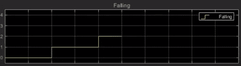
A Falling Edge Triggered Subsystem executes when the trigger signal changes from true (non-zero) to false (zero).
Key points include:
👉 Execution: On a falling edge of the trigger signal.
👉 Initialization: Similar to the rising edge, it can initialize states on the first trigger.
👉 Usage: Ideal for operations that need to occur when an event ends.
Applications Of Falling Edge Triggered Subsystem
a. Digital signal processing is used in digital systems, such as flip-flops, counters, and debouncing circuits, where certain actions must be performed in response to changes in input signals.
b. Event-Driven Systems: Perfect for applications like data recording, interrupt management, or state transitions in state machines where certain actions must be taken at particular times.
c. Control Systems: Helpful in triggering actions in response to changes in system states in a timely manner based on sensor inputs or control signals.
Either, Function Call, & Message Trigger Type
Trigger subsystems in Simulink can be set up to react to several kinds of trigger events, including messages, function calls, rising or falling edges, or either edge. You can create subsystems that carry out their internal logic in response to particular events or circumstances by using any of these trigger types. Below is a thorough description of every kind of trigger:
Either Edge Trigger
Every time the control signal changes from low to high (rising edge) or from high to low (falling edge), either edge trigger subsystem operates according to its internal logic. When you need to react to any change in the signal, independent of its direction, this kind of subsystem comes in handy.
Function Call Trigger
A Trigger for a Function Call Subsystem responds to a function call signal by carrying out its internal logic. With this kind of trigger, you can precisely control when the subsystem is executed, which is helpful for modeling systems where certain function calls require specific actions to be taken.
Trigger Message
When a message is received from another area of the model, a Message Trigger Subsystem responds by carrying out its internal logic. This kind of trigger facilitates asynchronous communication between model components and is helpful for event-driven systems where actions are started in response to messages.
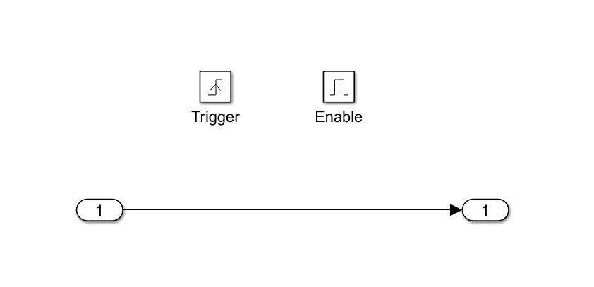
2.3. Enable-Triggered Triggered Subsystem
An advanced kind of subsystem in Simulink that combines the characteristics of both enabled and triggered subsystems is called an enable-triggered subsystem. This means that only when a particular triggering event takes place and an enable condition is met does it carry out its internal logic. Applications requiring conditional execution based on intricate criteria, including particular signal values and exact event timing, benefit greatly from this kind of subsystem.
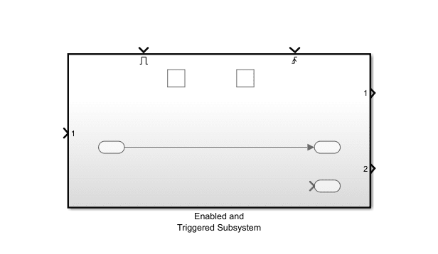
Enable Port: This port determines whether the subsystem is operational or not. Only when the enable signal is affirmative (non-zero) does the subsystem come to life. Regardless of the trigger signal, the subsystem stays inactive if the enable signal is 0 or negative.
Trigger Port: This port is used to identify particular events that set off the subsystem’s execution. Depending on the kind of trigger event (rising edge, falling edge, or either edge) set for the trigger port, the subsystem operates.
Execution Control: Only when it is both enabled and triggered does the Enable-Triggered Subsystem come into action. This dual condition makes sure that the internal logic of the subsystem only runs when certain, frequently complicated conditions are satisfied.
State Management: The subsystem offers flexibility in how state information is handled across enable/disable and trigger events by having the ability to maintain or reset its internal states between activations.
Event-Driven and Conditional Processing: This subsystem works well with event-driven systems that require certain events to trigger actions. It also works well with systems that have extra requirements for execution, including operating modes or signal thresholds.
Input using Signal Builder:
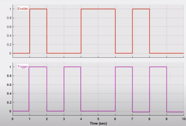
Output of Enable-Triggered Subsystem:
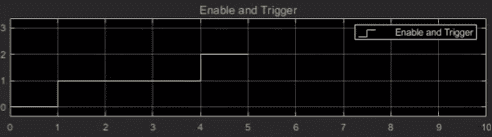
An Enable-Triggered Subsystem combines both enable and trigger mechanisms. It executes when it is enabled, and the trigger condition (rising or falling edge) is met. The subsystem must be enabled for the trigger condition to cause execution.
👉 Execution: When the enable signal is true and the trigger condition (rising/falling edge) occurs.
👉 Initialization: Can be configured for state behavior upon enable/disable and trigger.
👉 Usage: Useful when execution depends on both an enabling condition and a specific event.
Applications Of Enable-Triggered Subsystem
a. Control systems are helpful in control applications when certain events and operational conditions are required for actions to be taken, like safety interlocks that only activate under predetermined circumstances.
b. Digital signal processing is appropriate for synchronous digital circuits and state machines, among other systems that need to handle events precisely and execute commands conditionally.
c. Monitoring Systems: Perfect for data recording and surveillance systems that must only gather or handle data in certain situations.
This was about the “Difference Between Enable, Raising, Falling, Enable-Triggered Subsystem In Simulink”. Thank you for reading.
Also, read:
- 100 + Electrical Engineering Projects For Students, Engineers
- 1000+ Electronics Projects For Engineers, Diploma, MTech Students
- 1000+ MATLAB Simulink Projects For MTech, Engineering Students
- 50 Advanced Level Interview Questions On CAPL Scripting
- 500+ Embedded System Projects For Engineer, Diploma, MTech, PhD
- 500+ Matlab Simulink Projects Ideas For Engineers, MTech, Diploma
- 500+ Projects For Diploma Electrical, Electronics Student, Diploma Project
- 7 Ways EV Batteries Stay Safe From Thermal Runaway