
Troubleshooting CAN Communication Failures In A Test Environment
Hello guys, Welcome back to our blog. In this article, I will discuss troubleshooting CAN communication failures in a test environment and common CAN issues.
Ask questions if you have any electrical, electronics, or computer science doubts. You can also catch me on Instagram – CS Electrical & Electronics
- Code Generation In MATLAB Simulink, Things To Be Followed For Efficient Code Generation
- Variable-Step Solvers In MATLAB Simulink: Which One To Select
- Fixed-Step Solver In MATLAB Simulink: Which One To Select?
Troubleshooting CAN Communication Failures
Controller Area Network (CAN) is the backbone of modern vehicle communication, enabling Electronic Control Units (ECUs) to exchange data efficiently. Whether it’s for engine management, braking systems, or ADAS features, CAN plays a critical role in ensuring real-time communication and system reliability.
However, communication failures in a CAN network can disrupt diagnostics, real-time data exchange, and overall system performance. These failures may arise from physical layer issues, noise, incorrect baud rates, high bus loads, or faulty ECUs.
This article provides a structured troubleshooting approach to quickly diagnose and resolve CAN communication issues, ensuring optimal network performance in automotive testing environments.
Understanding CAN Communication
What is CAN Bus?
CAN (Controller Area Network) is a serial communication protocol designed for robust and reliable communication between multiple ECUs in a vehicle. It operates on a multi-master architecture, meaning multiple nodes can initiate communication without a central controller.
Key Components of CAN Communication
- CAN Nodes (ECUs): Control units in the vehicle that transmit and receive CAN messages.
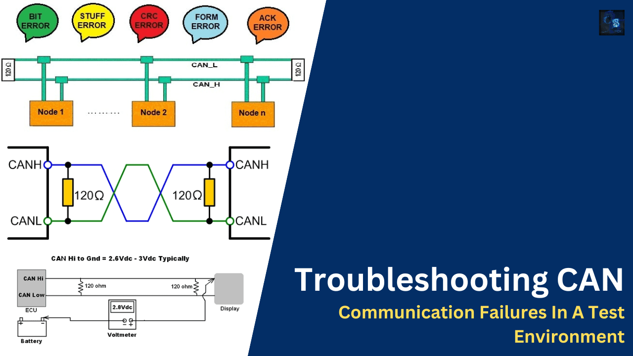
- CAN_H & CAN_L: Twisted-pair differential signals used for communication.
- Transceiver: Converts digital signals to CAN bus signals and vice versa.
- Termination Resistors (120Ω): These are required at both ends of the CAN bus for signal integrity.
- Arbitration Mechanism: Ensures message priority when multiple ECUs send data simultaneously.
Common CAN Communication Issues
- Lost messages or delayed transmissions
- Bus errors and arbitration failures
- Bus Off state (node stops communicating)
- Electromagnetic interference (EMI) affecting signals
- High bus load and data collisions
Step-by-Step CAN Bus Troubleshooting Guide
01. Checking Physical Layer Connections
The physical layer is the most common source of CAN failures. Start with these checks:
- Verify CAN_H & CAN_L wiring for breaks, loose connections, or corrosion.
- Use a multimeter to check continuity and short circuits.
Measure voltage levels:
- CAN_H: ~3.5V during transmission, ~2.5V idle
- CAN_L: ~1.5V during transmission, ~2.5V idle
- Inspect connectors and grounding to ensure proper shielding.
02. Verifying Termination Resistors
- Proper termination is critical to prevent signal reflections and noise.
- Measure resistance across CAN_H and CAN_L using a multimeter.
Expected value: ~60Ω (two 120Ω resistors in parallel).
- If resistance is higher, a termination resistor might be missing.
- If resistance is lower, there may be an extra resistor or a short circuit.
03. Monitoring Bus Load & Collisions
- A high bus load can cause message delays, arbitration failures, and retransmissions.
- Use tools like Vector CANoe, PCAN-View, or Kvaser CANalyzer to monitor bus utilization.
- The ideal bus load should be below 80%.
- Look for repeated message retransmissions or lost frames.
- Optimize message priorities and scheduling to reduce congestion.
04. Identifying Error Frames & Bus Off Condition
Error frames indicate communication problems. Excessive errors can put a node into Bus Off state, stopping all transmissions.
Use a CAN analyzer to check for:
- CRC errors
- Stuffing errors
- Acknowledgment errors
If a node enters Bus Off, reset it and investigate:
- Faulty transceiver or wiring
- Mismatched baud rates
- EMI or grounding issues
05. Validating Baud Rate & Bit Timing
- Mismatched baud rates across ECUs will prevent communication.
- Ensure all nodes operate at the same baud rate (125 kbps, 250 kbps, 500 kbps, or 1 Mbps).
- Verify the Bit Timing Register (BTR) settings to maintain proper synchronization.
- Use an oscilloscope to confirm bit timing accuracy.
06. Checking for Noise & Grounding Issues
- Electromagnetic noise can distort CAN signals, leading to errors.
- Use an oscilloscope to check for irregular signal fluctuations.
- Ensure all nodes share a common ground.
- Use twisted-pair cables and shielding to minimize interference.
- Identify and remove nearby high-power electrical sources that cause EMI.
07. Performing Node Isolation & Debugging
- A faulty ECU can disrupt the entire CAN network.
- Disconnect the ECUs one by one and monitor bus performance.
- Test individual nodes in loopback mode.
- Use a known-good test node to validate network behavior.
08. Analyzing CAN Logs & Diagnostic Trouble Codes (DTCs)
- Capture real-time CAN logs using a logger tool.
- Analyze OBD-II Uxxxx fault codes (e.g., U0001: High-Speed CAN Bus).
- Look for timeouts, unexpected disconnects, or repeated errors.
09. Checking Network Timing & Prioritization
- Lower CAN message IDs have higher priority.
- Ensure high-priority messages (e.g., safety-critical data) are not delayed.
- Optimize message transmission intervals to prevent congestion.
10. Retesting & Validating Stability
- Run automated test scripts to check network stability.
- Perform stress tests by simulating high bus loads and external noise.
- Verify that all nodes communicate reliably over extended periods.
Conclusion
A systematic approach to CAN troubleshooting ensures robust and reliable vehicle communication. By following these steps, engineers can quickly diagnose and resolve network issues, minimizing downtime and improving system stability.
Have you encountered CAN Bus failures before? Share your experiences and troubleshooting methods in the comments! 👇
CANBus #ECUValidation #AutomotiveTesting #EmbeddedSystems #HiLTesting #SoftwareTesting #ISO26262 #AutomotiveSoftware #CANCommunication #VehicleNetworking #AutomotiveElectronics #FunctionalSafety #ConnectedVehicles #OBD2 #IoT #CANFD #ADAS #EVTesting #DataLogging #DiagnosticTools #CANAnalyzer #VehicleSoftware #RealTimeSystems #SensorFusion #VehicleDiagnostics #AutomotiveR&D #AutomotiveInnovation