
Electronic Control Unit, ECU Flashing Process
Hello guys, welcome back to our blog. In this article, I will discuss the ECU flashing process or steps involved when flashing any software.
Ask questions if you have any electrical, electronics, or computer science doubts. You can also catch me on Instagram – CS Electrical & Electronics
- Guide On Writing Testcases For HiL Testing
- Everything You Need To Know About Sensor Fusion For Autonomous Driving
- System Pause, Driver Resume: The Art of Reclaiming Control
ECU Flashing Process
In the world of automotive electronics, Electronic Control Units (ECUs) play a pivotal role in controlling various functionalities within a vehicle, from engine management to advanced driver-assistance systems (ADAS). As vehicles evolve with increasing software complexity, the need for reliable, secure, and standardized flashing tools has grown substantially. One such tool is Vector’s VFlash, a popular utility for flashing ECUs in both development and production environments. This article delves deeply into the VFlash tool, its functionalities, and a step-by-step breakdown of the ECU flashing process.
What is ECU Flashing?
ECU flashing refers to the process of updating or programming the firmware or software into an ECU. The firmware stored on the ECU’s non-volatile memory controls the ECU’s behavior. Updates may be needed to fix bugs, enhance performance, meet regulatory changes, or introduce new features.
Flashing is typically carried out over communication protocols such as CAN (Controller Area Network), LIN (Local Interconnect Network), FlexRay, or Ethernet (DoIP).
Introduction to VFlash Tool
VFlash is a specialized flashing tool developed by Vector Informatik, designed to program ECUs using a pre-configured setup. It supports multiple communication protocols and is widely used across OEMs and Tier 1 suppliers. VFlash allows engineers to create a reusable configuration (VFlash project) that defines the ECU variant, communication interface, diagnostic protocol, and the flash files to be used.
Key Features of VFlash:
- Supports UDS, KWP2000, and manufacturer-specific protocols
- Compatible with various communication interfaces (CAN, FlexRay, Ethernet, LIN)
- GUI and command-line interface (CLI)
- Logging and error-tracking capability
- Secure flashing with Seed-Key authentication and encryption
VFlash Configuration Components
A typical VFlash setup includes:
- ECU Description File: Usually in A2L or CDD format
- Flash Data: The binary image to be written, in HEX, BIN, or S19 format
- VFlash Template: Pre-defined configurations for common ECUs
- Diagnostic Services: Used for session control, security access, download, and verification
- Communication Interface: Specifies how the PC connects to the vehicle or test bench
Step-by-Step Breakdown of the Flashing Process
The flashing process using VFlash is composed of multiple phases. Below is an in-depth explanation of each phase as displayed or logged in the VFlash tool.
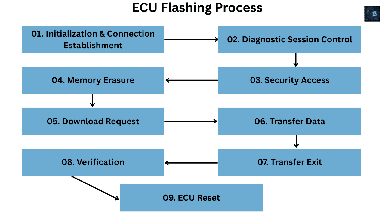
01. Initialization & Connection Establishment
The process starts with VFlash attempting to establish a connection with the target ECU over the chosen protocol. The tool sends initialization frames to wake the ECU, set up communication, and ensure it is ready to accept further diagnostic requests.
Common actions include:
- Wake-up signals (physical or network-based)
- TesterPresent (0x3E) service
- Verification of ECU presence
02. Diagnostic Session Control
Once communication is established, VFlash sends a DiagnosticSessionControl (0x10) service to switch the ECU from default to a programming-capable session.
Example:
- Request: 10 02 (Programming Session)
- Response: 50 02
The ECU must support the requested session and respond appropriately. Failing to enter the correct session may halt the flashing process.
03. Security Access
To prevent unauthorized reprogramming, most ECUs use a Seed-Key Security Access mechanism. VFlash handles this via the 0x27 service.
Steps involved:
- Send Seed Request: 27 01
- ECU responds with Seed: 67 01
- VFlash calculates and sends Key: 27 02
- ECU responds with success: 67 02
This security mechanism is OEM-specific and may involve custom algorithms or encryption.
04. Memory Erasure
Before new data can be written, existing firmware must be erased. This is typically handled by the RoutineControl (0x31) service.
Example:
- Request: 31 01 FF 00 (start erase routine)
- Response: 71 01 FF 00 (erase acknowledged)
Some ECUs also require sector-wise erase, which is handled by additional sub-functions and parameters.
05. Download Request
To begin data transfer, the flashing tool sends a RequestDownload (0x34) message with the address and length of the data block.
Example:
- Request: 34 00 44 00 00 00 10 00
- Response: 74 20 (positive response with block size)
This step sets up the conditions for chunked data transmission using TransferData services.
06. Transfer Data
The actual firmware is transferred using TransferData (0x36) messages. Each chunk is labeled with a block sequence counter.
Example:
- TransferData: 36 01
- Response: 76 01 (acknowledged)
- … repeated until all data is sent
VFlash automatically handles block size, sequence counting, and pacing.
07. Transfer Exit
Once all data has been transferred, the RequestTransferExit (0x37) service signals the end of the flashing operation.
Example:
- Request: 37
- Response: 77 (indicates successful completion)
At this point, the ECU internally validates the data using checksums or CRCs.
08. Verification
If configured, VFlash can instruct the ECU to verify the programmed image using a checksum verification routine.
- RoutineControl or custom service used
- Pass/fail result logged in GUI or command-line output
This step is crucial for ensuring that no data corruption occurred during transmission.
09. ECU Reset
The final step involves resetting the ECU to execute the newly programmed software.
- Service used: ECUReset (0x11)
- Request: 11 01 (Hard Reset)
- Response: 51 01
The ECU reboots and begins operation in normal mode, executing the new firmware.
Visual Feedback in VFlash Tool
The VFlash GUI provides clear visual feedback and logging:
- Progress Bar for each step
- Live Diagnostic Log showing UDS messages
- Status Summary (Success/Failure)
- Error Reporting with detailed traceability
- Timing Analysis (how long each phase took)
Security and Compliance Features
Modern ECUs demand secure flashing methods to protect against tampering and reverse engineering. VFlash supports:
- Encrypted Flash Files
- Seed-Key Algorithms with Custom DLLs
- Secure Boot Validation
- Anti-rollback protections
- Audit Logging for compliance
These features are critical in production environments, especially with increasing focus on automotive cybersecurity standards such as ISO/SAE 21434.
Use Cases of VFlash in Real-World Applications
- OEM Production Lines – Mass flashing of ECUs with traceability
- Field Updates – Service technicians are updating software at dealerships
- HIL Testing Environments – Flashing ECUs during simulation runs
- Prototype Development – Engineers testing new software builds quickly
Conclusion
The VFlash tool from Vector provides a reliable, versatile, and secure environment for ECU flashing in the automotive domain. Understanding each step in the flashing sequence—from session control to data transfer and reset—ensures smooth development, debugging, and deployment processes.
As ECUs become more complex and cybersecurity takes center stage, tools like VFlash will continue to play a crucial role in the automotive software ecosystem. Mastering this tool not only boosts productivity but also aligns with industry standards and best practices.
Whether you’re a developer, test engineer, or production specialist, a deep understanding of VFlash and the underlying diagnostic services it employs can greatly enhance your embedded software development lifecycle.
This was about “Electronic Control Unit, ECU Flashing Process“. Thank you for reading.
Also, read:
- 100 (AI) Artificial Intelligence Applications In The Automotive Industry
- 2024 Is About To End, Let’s Recall Electric Vehicles Launched In 2024
- 50 Advanced Level Interview Questions On CAPL Scripting
- 7 Ways EV Batteries Stay Safe From Thermal Runaway
- 8 Reasons Why EVs Can’t Fully Replace ICE Vehicles in India
- A Complete Guide To FlexRay Automotive Protocol
- Adaptive AUTOSAR Vs Classic AUTOSAR: Which One For Future Vehicles?
- Advanced Driver Assistance Systems (ADAS): How To Become An Expert In This Growing Field