
How to Perform Hardware-in-the-Loop (HiL) Testing with Simulink
Hello guys, welcome back to my blog. In this article, I will discuss how to perform hardware-in-the-loop testing with Simulink and what are the steps to be followed.
Ask questions if you have any electrical, electronics, or computer science doubts. You can also catch me on Instagram – CS Electrical & Electronics
- PREEvision: A Comprehensive Guide To Model-Based Automotive E/E Engineering
- Top 100 Automotive Companies And Their Career Portal Link
- Coding Based CAPL Script Interview Questions
How to Perform Hardware-in-the-Loop (HiL) Testing with Simulink
With the increasing complexity of automotive, aerospace, and industrial control systems, ensuring the reliability and accuracy of embedded software before deployment is crucial. Hardware-in-the-Loop (HiL) testing is a powerful technique that allows engineers to test embedded control systems in a simulated real-world environment. This enables the validation and verification of Electronic Control Units (ECUs) and embedded controllers without the need for full physical prototypes.
HiL testing bridges the gap between Model-in-the-Loop (MiL) and Software-in-the-Loop (SiL) simulations and actual real-world implementation, making it an essential step in the Model-Based Design (MBD) process. MATLAB and Simulink provide an extensive framework for performing HiL testing efficiently and accurately.
In this comprehensive guide, we will explore what HiL testing is, its benefits, and how to implement it using Simulink. We will also discuss real-time platforms, fault injection methods, and validation techniques used in automotive and other industries.
01. What is Hardware-in-the-Loop (HiL) Testing?
HiL testing is a real-time simulation technique where a control system (such as an ECU) is tested by interfacing it with a simulated physical system running on a HiL test bench. Instead of connecting an ECU to an actual physical system, a real-time simulation of the system is created, allowing the ECU to be tested in various conditions without risking hardware damage or safety issues.
Key Features of HiL Testing:
- Real-time simulation of plant models.
- Closed-loop testing with real sensors and actuators.
- Fault injection capabilities to test system robustness.
- Automated testing and validation of ECU software.
- Supports various communication protocols (CAN, LIN, FlexRay, Ethernet, etc.).
Industries Using HiL Testing
- Automotive (ECU validation, ADAS, powertrain, EV battery management systems)
- Aerospace (flight control systems, avionics)
- Industrial Automation (robotics, factory control systems)
- Energy Systems (smart grids, renewable energy control systems)
Benefits of HiL Testing
01. Reduces Development Time and Cost: HiL testing eliminates the need for expensive prototypes by allowing engineers to test control systems in a virtual environment. This accelerates product development and reduces costs associated with physical testing.
02. Enhances Safety and Reliability: Since HiL enables fault injection and testing under extreme conditions, it helps engineers identify system failures before deployment, improving overall reliability.
03. Enables Automated Testing and Regression Analysis: HiL test benches can run automated test scripts, allowing engineers to validate software changes without manual intervention. This makes it easier to perform regression testing and ensure that software updates do not introduce new errors.
04. Supports Compliance with Industry Standards: HiL testing is widely used for safety-critical applications that must comply with industry standards such as ISO 26262 (Automotive Functional Safety), DO-178C (Aerospace Software Certification), and IEC 61508 (Industrial Safety Systems).
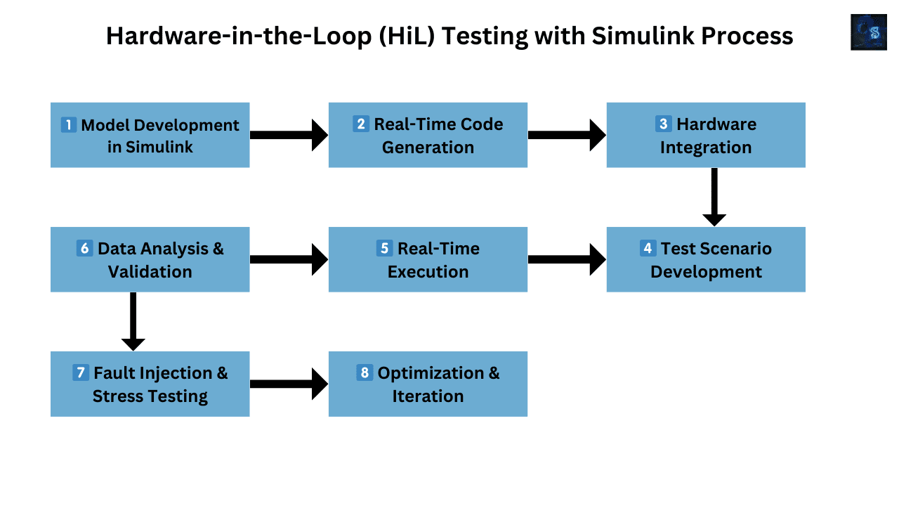
Performing HiL Testing with Simulink
Simulink, part of MATLAB, provides a robust environment for modeling, simulating, and implementing HiL test setups. Let’s explore the step-by-step process of performing HiL testing using Simulink.
Step 1: Develop the Plant Model in Simulink
The first step in HiL testing is to develop a plant model—a mathematical representation of the physical system being controlled. This model is built using Simulink’s block-based modeling environment.
- Define system dynamics (e.g., vehicle dynamics for an automotive system).
- Include sensor and actuator models.
- Use Simulink toolboxes (Control System Toolbox, Simscape, Vehicle Dynamics Blockset, etc.).
Step 2: Select a Real-Time Hardware Platform
To run the Simulink model in real time, you need a HiL platform such as:
- dSPACE Scalexio
- National Instruments (NI) PXI
- Speedgoat Real-Time Target Machine
- Opal-RT
These platforms interface with ECUs and execute the Simulink model in real time.
Step 3: Deploy Simulink Model to the HiL System
- Convert the Simulink model to C code using Simulink Coder & Embedded Coder.
- Compile and deploy the code onto the HiL hardware.
- Establish communication with the ECU using CAN, LIN, or Ethernet.
Step 4: Perform Real-Time Testing & Fault Injection
Once deployed, the HiL setup allows:
- Real-time monitoring of ECU outputs.
- Fault injection (e.g., sensor failures, incorrect signals) to test ECU response.
- Data logging & visualization using Simulink Real-Time and dSPACE ControlDesk.
Step 5: Analyze Results & Optimize Control Algorithm
- Compare real-time ECU behavior against Simulink reference data.
- Adjust control parameters and re-run simulations.
- Ensure compliance with safety standards.
Challenges & Best Practices in HiL Testing
Common Challenges
- High Initial Cost – HiL platforms and real-time hardware are expensive.
- Model Complexity – Developing accurate plant models requires domain expertise.
- Synchronization Issues – Ensuring the HiL system and ECU remain in sync is crucial.
Best Practices for HiL Testing
✅ Use Modular Plant Models – Helps in reusability and scalability.
✅ Automate Test Cases – Increases efficiency and ensures repeatability.
✅ Integrate with CI/CD Pipelines – Enables continuous validation in software development.
✅ Ensure Real-Time Constraints – Verify that the HiL system meets real-time execution requirements.
Future Trends in HiL Testing with Simulink
With the rise of autonomous vehicles and AI-driven control systems, HiL testing is evolving to support:
- Virtual HiL (vHiL) – Running HiL tests in the cloud using digital twins.
- Machine Learning Integration – AI-driven fault detection & predictive maintenance.
- 5G & V2X Communication Testing – Ensuring vehicle connectivity & real-time data processing.
Conclusion
HiL testing with Simulink is an essential step in the development of modern control systems, ensuring reliability, safety, and efficiency before deploying embedded software into real-world applications. By combining model-based design, real-time simulation, and automated testing, engineers can significantly reduce development costs, improve product quality, and enhance safety in automotive, aerospace, and industrial automation sectors.
Have you worked on HiL testing with Simulink? Share your experiences in the comments! 🚀
#HiLTesting #Simulink #ModelBasedDesign #ECUValidation #EmbeddedSystems #AutomotiveSoftware #RealTimeSimulation #ISO26262 #MATLAB #SoftwareDefinedVehicles #VehicleTesting #TechInnovation
This was about “How to Perform Hardware-in-the-Loop (HiL) Testing with Simulink“. Thank you for reading.
Also, read:
- 10 Tips To Maintain Battery For Long Life, Battery Maintainance
- 10 Tips To Save Electricity Bills, Save Money By Saving Electricity
- 100 (AI) Artificial Intelligence Applications In The Automotive Industry
- 100 + Electrical Engineering Projects For Students, Engineers
- 100+ C Programming Projects With Source Code, Coding Projects Ideas
- 1000+ Automotive Interview Questions With Answers
- 1000+ Control System Quiz, Top MCQ On Control System
- 1000+ Electrical Machines Quiz, Top MCQs On Electrical Machines