What Is DTR Structure, Materials, Estimation With Example
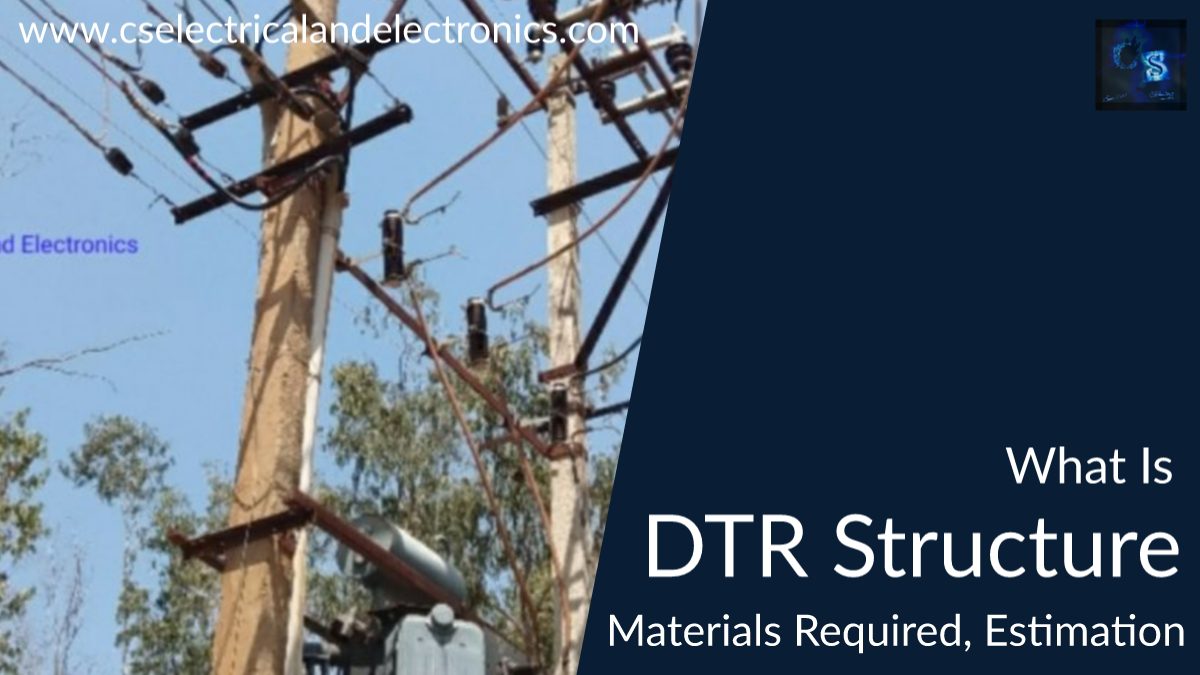
Hello Guys, welcome back to our blog. In this article, we will discuss what is DTR structure, the materials that are used in a double pole distribution transformer, and the estimation of the distribution transformer.
If you have any electrical, electronics, and computer science doubts, then ask questions. You can also catch us on Instagram – CS Electrical & Electronics.
Also, read:
- Applications Of Artificial Intelligence (AI) In Renewable Energy
- Top 100 Electrical Companies In The World Where You Can Work
- Difference Between 16-bit, 32-bit, And 64-bit Microcontrollers
DTR Structure
First, I will list some main materials used in the double pole DTR structure.
- Lightning Arrestors
- 11KV Horn Gap Fuse
- GOS (Gange Operating Switch)
- Distribution Transformer
- LT Metering Box
- Earthing System
The double-pole dtr structure is constructed using two poles, some horizontal cross-arms, clamps, nuts, and bolts.
Now we will tell you, leaving construction materials what are the other materials used in the DP structure?
First, I will tell you what is the purpose of the DP structure or distribution transformer structure,
The function of the DP structure is to step down the incoming voltage i.e., of 11 KV to 440 volts (three phases) or 230 volts (single-phase).
The materials used in the DP structure are :
1. Lightning Arresters
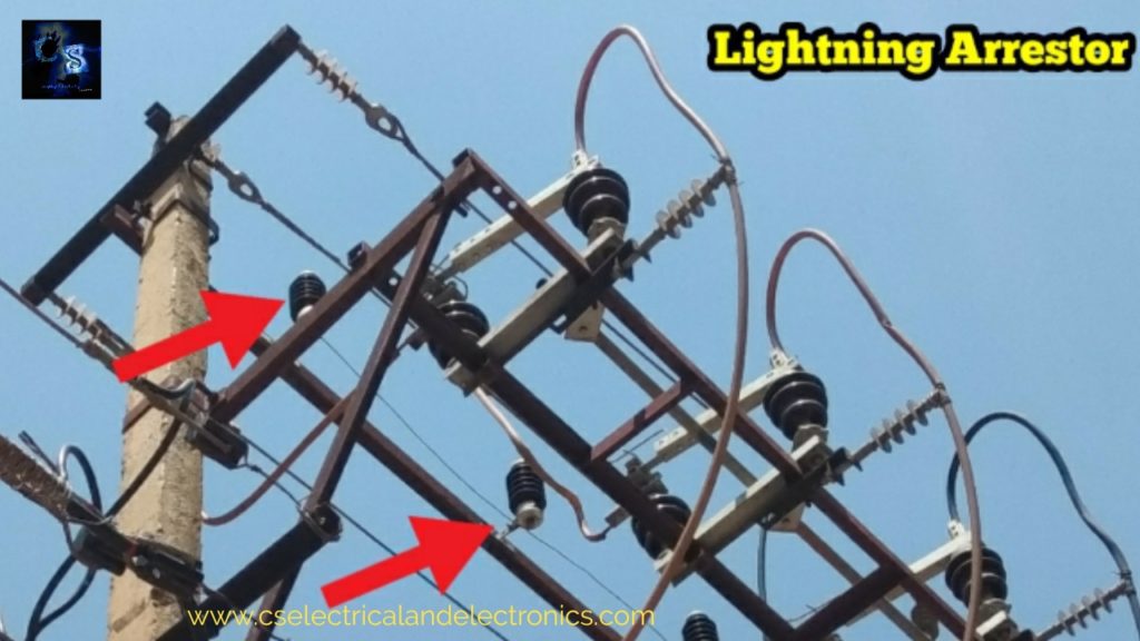
11 KV class lightning arrestors are used and lightning arrestors are fixed at the top of the DP structure as you can see in the above image. The function of the lightning arrestor is to protect the transformer from lightning tenders. When lightning occurs and falls on the structure the lightning arrestor transfers lightning stocks to the ground and thus protects the transformer. A total of three lightning arrestors are provided.
2. Fuse
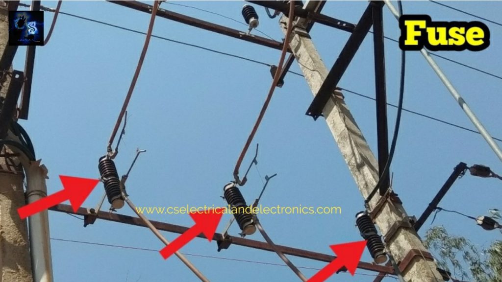
As you can see the fuse in the above image, is called a horn gap fuse for the protection of the transformer from overload and short circuit current. When overhead occurs on the ht line (11KV line), the fuse will isolate the circuit and thus protect the transformer.
3. GOS
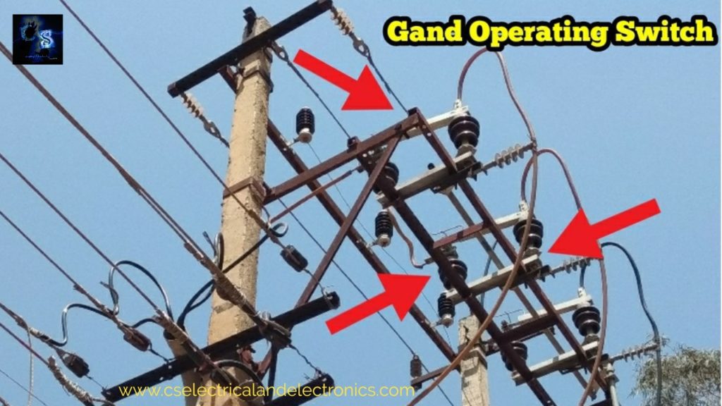
As you can see in the above image, it is called GOS or Gange operating switch.
The purpose of the gange operating switch is to isolate the circuit during repair conditions, By using the gange operating switch at a time all the lines can be disconnected.
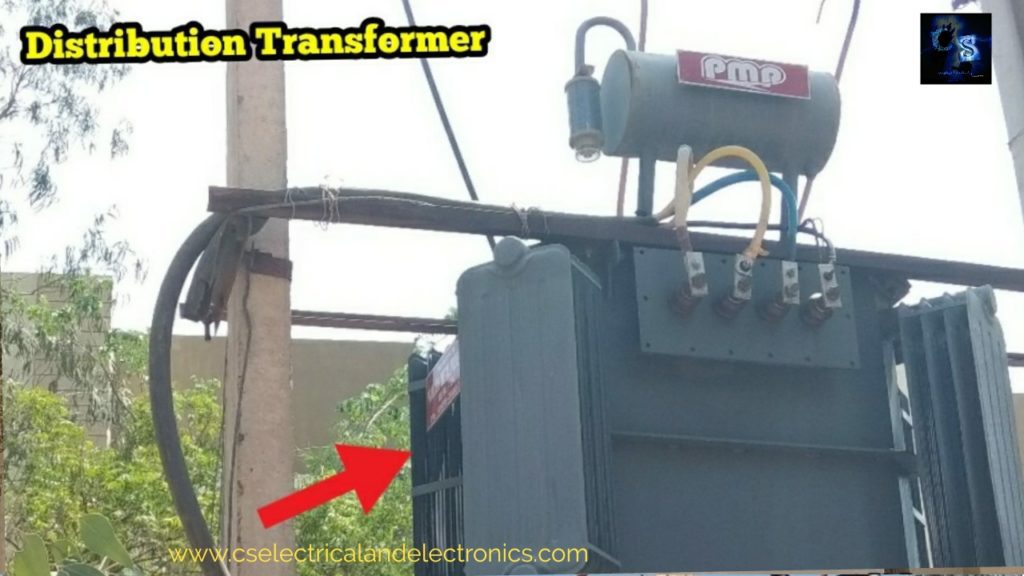
4. Distribution Transformer
The main purpose of the transformer is to step down the voltage from 11 KV to 440 volts ( three phases) or 230 volts (single-phase).
How to Calculate the Rating of Distribution Transformer
Q. Select a suitable transformer for an Industrial area. The load conditions are as follows :
- a. Available voltage = 11 KV
- b. Lighting load = 10 KW
- c. Demand factor = 0.7
- d. Required voltage = 440/230 volts
- e. Industrial load = 50 KW at 0.8 PF
- f. Diversity factor = 1.46
Solution :
Total connected load
= Lighting load + Industrial load
= (10 × 1) ÷ pf + (50 ×1) ÷ pf
= 10 + 62.5
= 72.5
Maximum demand
= Connected load × Demand factor
= 72.5 × 0.7
= 50.75 say 50 KVA
The required capacity of the transformer
= Maximum demand / Diversity factor
= 50 / 1.46
= 34.246 or say 34 KVA
Allowance for future expansion at 20 % of the required capacity
= 34 × 0.2
= 7 KVA
Hence capacity of the transformer = 34 + 7 = 41
(41 KVA, 11 KV/440 V 3 -phase is not available)
Market availability = 50 KVA
Therefore, a transformer of 50 KVA, 11 KV/440 V, 3-phase delta-star, 50 Hz is selected.
Q. A small workshop has the following load to find the transformer capacity required.
- a. A 1 HP, 400 V, 3-phase for drilling machine
- b. A 1/2 HP, 230 V, single phase for Grinding machine
- c. A 3 HP, 400 V, 3-phase motor for lathe machined
- d. A 5 KVA, 230 V, welding transformer.
- e. A milling machine 5 HP, 400 V, 3-phase
- f. A power Backsaw, 3 HP, 400 V, 3-phase.
- g. Two power sockets
- h. Lamp loads – 25 points
- i. Ceiling fans – 15 nos
- j. Two numbers, high-pressure mercury vapor lamps of 500 W, 1-phase, 230 V, 50 Hz, supply.
Calculate the total connected load. If the demand factor is 0.6 and the diversity factor is 1 %.
Solution :
(a) All three-phase motor loads 12 Hp assuming Pf 0.8 and efficiency 85 %
Therefore, VA = (HP × 735.5) ÷ (efficiency × Pf)
= (12 × 735.5) ÷ (0.85 × 0.8) = 7853 VA
(b) Taking all single-phase loads :
Power sockets – 2 × 1000 = 2000 w
Lamps – 25 × 40 = 1000 w
Ceiling fans – 15 × 80 = 1200 w
Mercury vapour lamps – 500 × 2 = 1000 w
1/2 HP Grinder – (05 × 735.5) ÷ (0.8 × 0.6)
= 766 / 5966 (efficiency = 08 & Pf = 0.6)
(c) 5 KVA welding transformer – 5000 VA
The total load in VA
= 7853 + 5966 + 5000
= 18819 VA
= 18.819 KVA
Actual demand
= connected load × demand factor
= 18.819 × 0.6
= 11.2914 KVA
The required capacity of the transformer
= Actual demand/diversity factor
= 11.2914 / 1.10
= 10 KVA
Allowance for future expansion at 25 % of the required capacity
= 10 × 1.25
= 12.83 KVA.
Market availability = 15 KVA
Hence, a transformer of 15 KVA, 11 KV/440 V, 3-phase delta-star, 50 Hz is selected.
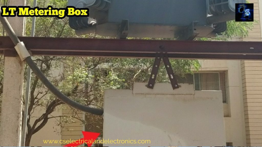
5. LT Metering Box
LT metering box consists of some relays, meters, etc. LT metering box will be placed at the bottom of the structure.
6. Earthing System
A total of three no of earthing will be provided for the DP structure, one earth will be connected to the lightning arrester, another earthing will be connected to the transformer neutral, and the third earthing will be connected to all the parts of the DP structure.
All the earthing are also interconnected to each other.
So, guys, these are some materials that are used in the double pole dtr structure.
Tags: What Is DTR Structure, Materials, Calculation, DTR Structure, double pole DTR structure, How to calculate the rating of a transformer, double pole DTR structure, pole-mounted substation.
Also, read:
- 10 Tips To Maintain Battery For Long Life, Battery Maintainance
- 10 Tips To Save Electricity Bills, Save Money By Saving Electricity
- 100 (AI) Artificial Intelligence Applications In The Automotive Industry
- 100 + Electrical Engineering Projects For Students, Engineers
- 1000+ Automotive Interview Questions With Answers
- 1000+ Control System Quiz, Top MCQ On Control System
- 1000+ Electrical Machines Quiz, Top MCQs On Electrical Machines
- 1000+ MATLAB Simulink Projects For MTech, Engineering Students
Very informative