Hello guys, welcome back to our blog. Here in this article, we will discuss what is J1939 in Automotive, the working of J1939, what is the purpose of it, and its applications of J1939.
Ask questions if you have any electrical, electronics, or computer science doubts. You can also catch me on Instagram – CS Electrical & Electronics.
Also, read:
- Difference Between CC, LIM, ACC, And ACCP In Automotive
- Why PMSM Is Very Popular In Electric Vehicles?
- Why ESP32 Is Better Than Arduino, Which Is Best?
J1939 In Automotive
Heavy-duty vehicle manufacturers primarily employ SAE J1939, a high-level communication protocol built on the Controller Area Network (CAN), in their operations. This protocol makes it easier for different Electronic Control Units (ECUs) in a car, like the gearbox control module, engine control module, and other systems, to seamlessly exchange data. J1939, created by the Society of Automotive Engineers (SAE), is a standard for communication between components from different manufacturers. This is important since current heavy-duty cars have complex systems that require interoperability and quick data transfer.
The J1939 protocol uses the CAN bus, a strong automotive bus standard made for dependable, fast communication in challenging circumstances. The foundation of J1939 is CAN bus technology, which offers reliable message delivery mechanisms, fault confinement, and error detection. Higher-layer protocols that specify the structure and interpretation of data are added to the CAN protocol by J1939, allowing for more intricate control and communication duties. The hierarchical structure of J1939 enables it to manage the complexity of contemporary car systems, guaranteeing precise and effective data transfer between ECUs.
The organization and identification of data using Parameter Group Numbers (PGNs) and Suspect Parameter Numbers (SPNs) is a fundamental component of J1939. PGNs classify communications according to their purpose and content, whereas SPNs define specific parameters in these messages. Precise data identification and retrieval are made possible by this organised method, which is crucial for system monitoring and diagnostics. To enable other systems to read and react to these parameters in real time, an engine control unit, for instance, might broadcast a PGN containing SPNs for engine speed, temperature, and fuel rate.
Comprehensive diagnostic capabilities are supported by J1939 and are essential for preserving vehicle performance and safety. Diagnostic Trouble Codes (DTCs), which mark system failures or poor performance, can be reported and retrieved thanks to the protocol. J1939 gives technicians a standardized diagnostic approach that speeds up problem identification and resolution, lowering maintenance expenses and downtime. Furthermore, the protocol allows for the real-time recording and monitoring of vehicle performance data, which is beneficial for fleet management and predictive maintenance.
Because of its flexibility and scalability, the protocol can be applied to a variety of heavy-duty vehicle applications. Whether it is utilised in construction equipment, buses, trucks, or agricultural gear, J1939 guarantees dependable control and communication among various vehicle systems. Because of its plug-and-play design, adding additional components and devices is simple, allowing for upgrades and expansions without requiring extensive reconfiguration. In businesses where vehicles need to adjust to changing operational requirements and technological improvements, this flexibility is very helpful.
To sum up, SAE J1939 is a crucial communication protocol for the automotive sector, especially for trucks and heavy-duty cars. Its sturdy CAN-based architecture, together with PGNs and SPNs’ structured data organization, offers a dependable and effective method of communication between car systems. Thanks to J1939’s broad diagnostic capabilities and adaptability to a variety of applications, contemporary cars can run smoothly, effectively, and safely. J1939 continues to be essential to the creation and upkeep of cutting-edge car systems as automotive technology develops.
Overview of Controller Area Network
Originally created for the automotive industry, particularly for European cars, the Controller Area Network (CAN) is a serial network technology that is now widely used in industrial automation and other fields. As its name suggests, the CAN bus is a network technology that enables quick communication between microcontrollers up to real-time requirements. It is largely utilized in embedded systems and replaces the far more complex and expensive Dual-Ported RAM technology.
CAN is a high-speed, two-wire, half-duplex network technology that is more reliable and functional than traditional serial technologies like RS232, but it can be implemented at a lower cost.
For example, TCP/IP is designed to transport large amounts of data, but CAN is meant to be used in real-time scenarios. With its 1 MBit/sec baud rate, CAN easily outperforms a 100 MBit/sec TCP/IP connection in terms of quick error recovery, quick error detection, and quick error repair.
CAN networks can serve as both an open communication channel for intelligent devices and an embedded communication system for microcontrollers. Certain users, such as those in the medical engineering profession, chose to adopt CAN due to the need to comply with extremely strict safety regulations.
Manufacturers of other equipment with extremely high safety or dependability standards, such as transportation systems, robots, and lifts, have to take similar needs into account.
The combination of less wire and clever message collision prevention—which ensures that no data is lost during message transmission—is the biggest benefit of the Controller Area Network.
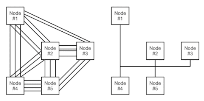
Without CAN & With CAN
An overview of the technical features of CAN is provided in the following.
Controller Area Network
- It is an embedded solutions serial networking technology.
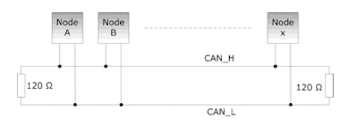
- Just two wires, CAN_H and CAN_L, are required.
- Operates at up to 1 megabit per second of data rate.
- Up to 8 bytes per message frame are supported.
- Only supports message IDs; node IDs are not supported. Many message IDs can be supported by a single application.
- Supports message priority, where a message’s priority increases with a lower message ID.
- Supports the 11-bit standard message ID and the 29-bit extended message ID.
- Do not encounter message collisions (which other serial technologies may cause).
- It is not strict when it comes to cable regulations. It is adequate to use twisted-pair wiring.
SAE J1939 Higher Layer Protocol
While CAN is very useful in cars and small embedded systems, it is not appropriate for projects that need at least some network management or messages containing more than eight data bytes.
Consequently, in order to provide an improved networking technology that supports messages of unlimited length and allows network management, including the use of node IDs (CAN supports only message IDs where one node can manage multiple message IDs), higher layer protocols (additional software on top of the CAN physical layer) such as SAE J1939 for vehicles were designed.
SAE J1939
- It is a specification created by SAE, the Society of Automotive Engineers.
- Defines vehicle network (trucks, buses, farm equipment, etc.) communication.
- It is a higher-layer protocol with the physical layer being CAN.
- Uses a twisted pair of shielded wire
- Applies a 40-meter (~120-foot) maximum network length.
- Applies a 250 Kbit/sec standard baud rate.
- Allows for a maximum of 253 controller applications (CA), where one ECU can oversee several CAs. Allows for a maximum of 30 nodes (ECUs) in a network
- Facilitates broadcast and peer-to-peer communication
- Allows messages up to 1785 bytes in length.
- Establishes a collection of established vehicle parameters known as parameter group numbers, or PGNs.
- Facilitates network management (node IDs and address claiming process included)
Four essential features of J1939
01. Baud rate of 250 Kbps and a 29-bit extended ID
Typically, the J1939 baud rate is 250K, however, it can now support 500K. The identifier is extended 29-bit (CAN 2.0B).
02. Broadcast + on-request data
While certain data is only available by requesting it via the CAN bus, the majority of J1939 messages are broadcast on the CAN bus.
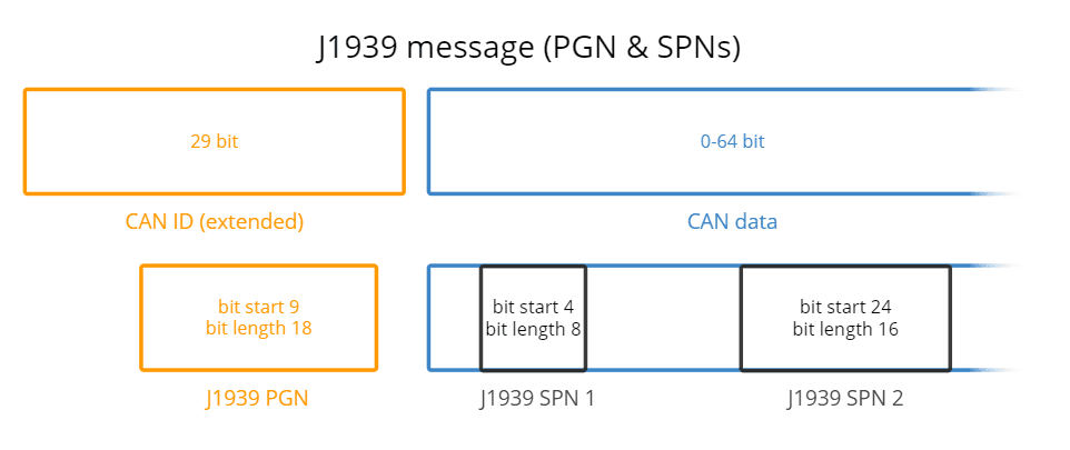
03. SPN parameters and PGN identifiers
18-bit Parameter Group Numbers (PGN) are used to identify J1939 communications, while J1939 signals are referred to as Suspect Parameter Numbers (SPN).
04. Multi-packets and multibyte variables
The least significant byte of multibyte variables is sent first (Intel byte order). PGNs using the J1939 transport protocol can have up to 1785 bytes of storage.
J1939 PGN and SPN
Parameter Group Number (PGN)
An 18-bit subset of the 29-bit extended CAN ID makes up the J1939 PGN. To put it simply, the PGN is a special frame number in the J1939 standard. You can, for instance, look up this information in the PGNs/SPNs list found in the J1939-71 standard specification.
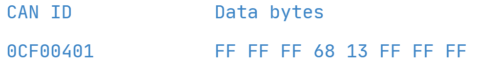
Assume that HEX ID 0CF00401 appears in a J1939 message you recorded. In this case, the PGN has a length of 18 (indexed from 1) and begins at bit 9.
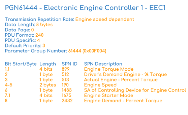
The resultant PGN, or decimal number 61444, is 0F004. You may identify this as the “Electronic Engine Controller 1 – EEC1” by looking it up in the SAE J1939-71 specification. Additionally, the document will include information about the PGN, such as priority, transmission rate, and a list of SPNs that are connected to it (see the figure). There are seven SPNs (such as Engine Speed and RPM) associated with this PGN; more information may be found for each of these SPNs in the J1939-71 datasheet.
Comprehensive analysis of the J1939 PGN
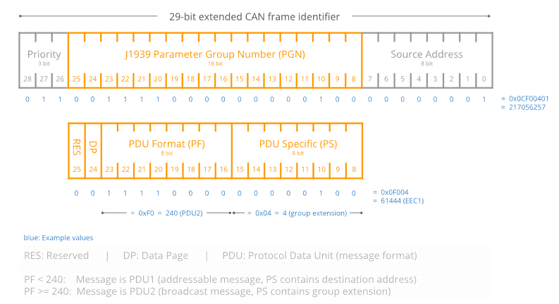
Let’s take a closer look at the CAN ID to PGN conversion.
The J1939 PGN (18 bits), the Source Address (8 bits), and the Priority (3 bits) make up the 29-bit CAN ID. The Reserved Bit (1 bit), Data Page (1 bit), PDU format (8 bit), and PDU Specific (8 bit) can then be separated out of the PGN.
Additionally, example values in binary, decimal, and hexadecimal formats are provided for each field in the comprehensive PGN illustration.
See also our online CAN ID to J1939 PGN converter to find out more about the conversion from 29-bit CAN ID to 18-bit J1939 PGN. For PGNs contained in our J1939 DBC file, the converter furthermore provides a complete J1939 PGN list.
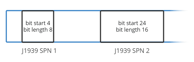
Suspect Parameter Number (SPN)
The CAN signals (parameters) that are present in the databytes are uniquely identified by the J1939 SPN. SPNs can be characterised by their bit start position, bit length, scale, offset, and unit—information needed to extract and scale the SPN data to physical values—and are grouped by PGNs.
Engine Speed: Exacting J1939 SPN 190
You may determine that this is the previous PGN 61444 by translating the may ID to the J1939 PGN. You can see from the J1939-71 document that Engine Speed (SPN 190), with information as shown in the figure below, is one of the SPNs included in this PGN.
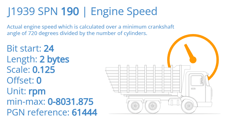
It is feasible to extract the Engine Speed physical value data using these details, for example, in order to create a visualization. To accomplish this, observe from the SPN information that bytes 4 and 5, or the HEX data bytes 68 and 13, contain the pertinent data. By taking the HEX number 1368 (Intel byte order) and converting it to decimal representation, we obtain 4968. We scale this value using the offset 0 and the scale 0.125 RPM/bit to determine the RPM.
621 RPM is the physical value, often known as the scaled engineering value.
In the automobile sector, SAE J1939 is used to provide structured and standardized communication between different Electronic Control Units (ECUs) in a vehicle. Here’s a thorough explanation of how J1939 functions:
01. Foundational CAN Bus Technology
The Controller Area Network (CAN) bus, a strong and dependable communication protocol created by Bosch, is the foundation of SAE J1939. High-speed data transfer, error detection, and fault tolerance are all made possible by the CAN bus and are essential for automotive applications. Every ECU in a J1939 network is linked to the CAN bus, enabling data transmission and reception throughout the network. Even in the loud surroundings that are typical of automotive situations, the CAN bus makes sure that messages are delivered.
02. Identification and Message Structure
Messages in J1939 are uniquely recognised by Parameter Group Numbers (PGNs). Every PGN specifies a certain message type and format, such as vehicle speed or engine temperature. Individual data points in these messages are designated with Suspect Parameter Numbers (SPNs). SPNs for parameters like engine RPM, oil pressure, and coolant temperature, for instance, might be included in a message including a PGN for engine data. Because of the exact organisation and retrieval of data made possible by this organised method, every ECU is guaranteed to comprehend and process the information it receives with accuracy.
03. Broadcast Communication
Messages are sent to every node (ECU) on the network under the J1939 paradigm of broadcast communication. Based on its PGN, each ECU can determine whether to read or disregard a message. The network design is made simpler by this broadcast technique since it eliminates the requirement for direct point-to-point connection between ECUs. For example, all other ECUs, including those controlling the gearbox, brakes, and instrument clusters, have access to engine speed data broadcast by the engine control unit. These ECUs may need this information in order to carry out their respective tasks.
04. Setting Priorities and Using Arbitration
The prioritisation mechanism of J1939 is a crucial characteristic since it guarantees the transmission of higher-priority information first. A priority field is a part of every J1939 message’s identification. The arbitration process of the CAN protocol settles disputes when several ECUs try to transmit at the same time by letting the message with the highest priority to continue. In automotive systems, where specific data, like emergency brake commands, must be communicated immediately to ensure vehicle safety, this prioritisation is crucial.
05. Troubleshooting and Defect Finding
Comprehensive diagnostic features are supported by J1939 and are essential for vehicle upkeep and troubleshooting. Diagnostic Trouble Codes (DTCs) are signals that an ECU detects a malfunction or problem. These DTCs are standardised codes that represent certain problems with the car’s systems, such misfiring engines or failing sensors. These codes can be retrieved by diagnostic tools via a J1939 network connection, which enables personnel to rapidly diagnose and fix issues. J1939 also facilitates real-time vehicle performance parameter monitoring, which helps with predictive maintenance and lowers downtime.
06. Instantaneous Interoperability
Plug-and-play functionality is a major benefit of J1939; it makes it simple to include new ECUs and devices into the car’s network. The new components don’t need a lot of reconfiguring to integrate with the current systems as long as they follow J1939 specifications. Vehicle makers and fleet operators stand to gain greatly from this interoperability, which makes it possible for them to effectively develop and enhance vehicle functionalities. For example, it is possible to upgrade the engine control system or install a new telematics module without significantly impacting the current network.
Applications Of J1939
SAE J1939 is widely used for engine control and monitoring in automobiles and commercial vehicles. It is essential for controlling different engine parameters. J1939 is used by Electronic Control Units (ECUs) to transmit vital information including fuel use, engine speed, and temperature. For example, efficient fuel consumption and transmission shift optimisation depend on engine RPM data transmitted over J1939. Likewise, J1939’s real-time temperature monitoring aids in the management of cooling systems, guarding against overheating and guaranteeing peak engine performance.
J1939 is also crucial for the smooth integration of gearbox systems with other car systems. In order to determine the optimal gear shifts depending on the engine’s current load and speed, transmission control units employ J1939 to receive data from the engine control unit. Improved fuel efficiency and seamless transitions are guaranteed by this communication. Furthermore, clutch control is optimised with information from several sensors, extending the life and dependability of the gearbox.
The coordination and operation of sophisticated braking technologies, such as Electronic Braking Systems (EBS) and Anti-lock Braking Systems (ABS), depend on J1939 in braking systems. To provide rapid and efficient braking, the brake control unit transmits and receives braking commands and feedback using J1939. In emergency scenarios, the ABS must share real-time data on wheel speed and brake pressure in order to prevent wheel lock-up and preserve vehicle control.
The extensive diagnostic features of J1939 greatly improve vehicle diagnostics and maintenance. When faults are discovered, ECUs have the ability to broadcast Diagnostic Trouble Codes (DTCs), which facilitates the prompt identification and resolution of issues. With the ability to schedule repairs before serious failures arise, real-time monitoring helps with predictive maintenance, which lowers maintenance costs and vehicle downtime. Additionally, performance data from the J1939 network may be retrieved by technicians using diagnostic tools, which speeds up troubleshooting and repair procedures.
J1939 is used by telematics and fleet management systems to gather and send data that is essential for large fleet management. Fleet management centers get real-time data on the position, speed, and operating state of vehicles, facilitating efficient tracking and administration. Route optimization, fuel efficiency, and timely maintenance are all aided by this data. By improving decision-making, performance analytics based on J1939 data can raise fleet productivity and efficiency.
Additionally, J1939 enhances the overall driving experience by supporting comfort and body control systems. In order to maintain passenger comfort, climate control systems use J1939 to modify the cabin temperature in response to information from several sensors. J1939 is also used to control lighting, integrating outside and inside lighting for convenience and safety. In order to give drivers real-time information on vehicle speed, engine RPM, and warning indicators for crucial conditions like low fuel or engine issues, instrumentation and display systems rely on J1939. In order to improve vehicle safety and driver convenience, Advanced Driver Assistance Systems (ADAS), such as collision avoidance and lane departure warnings, also rely on J1939 for data interchange between sensors and control units.
This was about “What Is J1939 In Automotive, It’s Working, Purpose, Applications”. I hope this article may help you all a lot. Thank you for reading.
Also, read:
- 10 Free ADAS Projects With Source Code And Documentation – Learn & Build Today
- 100 + Electrical Engineering Projects For Students, Engineers
- 100+ Indian Startups & What They Are Building
- 1000+ Automotive Interview Questions With Answers
- 1000+ Electronics Projects For Engineers, Diploma, MTech Students