Hello guys, welcome back to our blog. In this article, I will discuss the XCP protocol or universal measurement and calibration protocol, its working, architecture, and commands.
Ask questions if you have any electrical, electronics, or computer science doubts. You can also catch me on Instagram – CS Electrical & Electronics
- Designing An Automotive Test System For ECU Validation
- Top 30 Automotive-Specific ISO Standards Every Automotive Engineer Must Know
- Hazard Identification Techniques In Functional Safety (FuSa) ISO 26262
XCP (Universal Measurement And Calibration Protocol)
In modern automotive and embedded systems, efficient communication protocols are essential for real-time measurement, calibration, and flashing of electronic control units (ECUs). One such widely used protocol is XCP (Universal Measurement and Calibration Protocol). Developed by the Association for Standardization of Automation and Measuring Systems (ASAM), XCP is an evolution of CCP (CAN Calibration Protocol) and provides high flexibility and efficiency across various transport layers.
This guide covers all aspects of XCP, including its architecture, working principles, transport layers, use cases, benefits, and comparison with other protocols.
01. What is XCP?
XCP (Universal Measurement and Calibration Protocol) is a standardized protocol for measuring and calibrating ECUs in real time. It enables fast, efficient, and flexible data acquisition, calibration, and flashing functionalities via different transport layers such as CAN, Ethernet, FlexRay, and SPI.
1.1 History and Development
- Developed by ASAM (Association for Standardization of Automation and Measuring Systems)
- Successor of CCP (CAN Calibration Protocol)
- Designed to be transport-independent, unlike CCP, which was limited to CAN
1.2 Key Features
- Transport-independent: Works over CAN, Ethernet, FlexRay, and other transport layers
- High performance: Supports high-speed data acquisition and large data volumes
- Standardized structure: Compatible with various tools and software solutions
- Flexibility: Supports dynamic memory allocation and real-time calibration
- Security: Offers encryption and authentication mechanisms
1.3 Transport Layers
XCP can be implemented on various transport layers:
| Transport Layer | Protocol Used |
| XCP on CAN | ISO 11898 |
| XCP on Ethernet | TCP/IP |
| XCP on FlexRay | FlexRay Protocol |
| XCP on USB | USB Protocol |
02. XCP Architecture and Working Principle
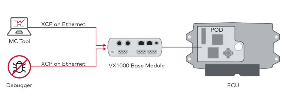
XCP follows a master-slave architecture where the master (calibration tool) communicates with one or multiple slaves (ECUs).
2.1 XCP Master-Slave Architecture
- Master: Typically a PC-based calibration and measurement tool (e.g., ETAS INCA, Vector CANape, dSPACE ControlDesk)
- Slave: ECU running XCP software stack, responding to commands from the master
2.2 XCP Communication Model
XCP communication consists of:
- Commands: Sent by the master to the slave to request specific actions
- Responses: Sent by the slave to confirm the execution of commands
- DAQ (Data Acquisition) Lists: Used for real-time data measurement
- STIM (Stimulation) Lists: Used to send data to the ECU for control purposes
2.3 XCP Message Structure
XCP messages contain the following:
PID (Packet Identifier): Identifies the type of XCP message being sent.
- 0xFF – Command message
- 0xFE – Response message
- 0xFD – Error message
- 0xFC – Event message
Command/Response Data: Each command is followed by data fields that define the requested operation. The response from the ECU contains acknowledgment, requested data, or error information.
Error Handling Information: If an error occurs, the ECU returns an error response (0xFD) with a specific error code.
Example error response:
0xFD 0x21 // ERR_ACCESS_DENIED
Example XCP Command and Response
a. Initialization – Connecting to ECU
Command: Connect Request (Master → Slave)
0xFF 0x00 0x00 0x00 0x00 0x00 0x00 0x00 // Connect command
Response: Connect Confirmation (Slave → Master)
0xFE 0x00 0x00 0x00 0x00 0x00 0x00 0x00 // Successful connection response
b. Read Memory – Retrieve Calibration Parameter
Command: Read Memory (Master → Slave)
0xFF 0x00 0x10 0x00 0x00 0x04 0x00 0x00 // Read memory command (4 bytes from address 0x1000)
Response: Memory Content (Slave → Master)
0xFE 0x00 0x12 0x34 0x56 0x78 // Data from requested memory location
c. Write Memory – Modify Calibration Parameter
Command: Set Calibration Value (Master → Slave)
0xFF 0x00 0x20 0x00 0x05 0xAA 0xBB 0xCC // Write 3 bytes (0xAA, 0xBB, 0xCC) to address 0x2000
Response: Acknowledge (Slave → Master)
0xFE 0x00 0x00 // Acknowledge successful calibration
d. Start Data Acquisition (DAQ)
Command: SET_DAQ_LIST_MODE
0xFF 0xE0 0x01 0x00 0x00 0x01
Response: Acknowledge
0xFE 0x00
03. Transport Layers Supported by XCP
One of the major advantages of XCP over CCP is its support for multiple transport layers. The following transport layers are commonly used:
3.1 XCP on CAN (XCP-on-CAN)
- Used in traditional automotive applications
- Limited by CAN’s bandwidth (1 Mbps)
- Suitable for low-speed applications
3.2 XCP on Ethernet (XCP-on-Ethernet)
- High-speed alternative to CAN, supporting 1 Gbps+ bandwidth
- Preferred for complex ECUs and high-speed logging
- Enables cloud-based diagnostics and calibration
3.3 XCP on FlexRay (XCP-on-FlexRay)
- Used in safety-critical applications
- Higher bandwidth than CAN, with deterministic communication
3.4 XCP on SPI (XCP-on-SPI)
- Used in embedded systems and chip-level communications
- Offers low latency and high-speed data exchange
04. XCP Protocol Features
4.1 Measurement & Calibration
- Online and Offline Calibration: Enables parameter tuning without affecting ECU operation
- Real-time Measurement: Supports high-frequency data logging
4.2 Flash Programming
- XCP allows for firmware updates and the reprogramming of ECUs
- Faster than traditional UDS-based flashing
4.3 Security Mechanisms
- Seed & Key Authentication
- Secure XCP (S-XCP) with encryption
05. Setting Up XCP in Vector CANoe
To set up XCP communication in Vector CANoe, follow these steps:
Step 1: Configure the CANoe Environment
- Open Vector CANoe.
- Create a new configuration or open an existing one.
- Add the XCP Transport Layer under the Network Hardware Configuration.
Step 2: Add the XCP Protocol
- Navigate to Database and select Add Protocol.
- Choose XCP on CAN (or another transport layer like XCP on Ethernet).
Step 3: Load the A2L File
- Go to System Variables and click Import A2L.
- Load the A2L (ASAP2) file that contains ECU calibration information.
Step 4: Establish Communication
- Start the CANoe measurement.
- In the Simulation Setup, select XCP Master and connect to the ECU.
Conclusion
XCP is a powerful protocol for ECU measurement and calibration, widely used in the automotive industry. With tools like Vector CANoe, engineers can efficiently interface with ECUs, perform calibration, and validate automotive systems.
By following this guide, you can set up XCP communication, execute commands, and troubleshoot ECU interactions effectively.
Automotive #XCP #CANoe #ECU #VehicleTesting #AutomotiveEngineering #EmbeddedSystems #Calibration #Measurement #CANProtocol #FlexRay #Ethernet #USB #VectorCANoe #ECUCommunication #DataAcquisition #ECUTesting #ASAM #Autosar #EmbeddedSoftware #AutomotiveElectronics #RealtimeSystems #VehicleDiagnostics #ISO11898 #ECUFlashing #SoftwareDevelopment #AutomotiveSoftware #AutomotiveIndustry #VectorTools #DataLogging #AutomotiveTesting #HILTesting #DSPACE #INCA #VehicleSafety #SignalProcessing #SystemIntegration #AutomotiveStandards #EngineeringTools #ProtocolTesting #CANBus
This was about “XCP (Universal Measurement And Calibration Protocol) – A Complete Guide“. Thank you for reading.
Also, read:
- “Mother of All Deals”: How The EU–India Free Trade Agreement Can Reshape India’s Economic Future
- 10 Free ADAS Projects With Source Code And Documentation – Learn & Build Today
- 100 (AI) Artificial Intelligence Applications In The Automotive Industry
- 1000+ Automotive Interview Questions With Answers
- 2024 Is About To End, Let’s Recall Electric Vehicles Launched In 2024
- 2026 Hackathons That Can Change Your Tech Career Forever
- 50 Advanced Level Interview Questions On CAPL Scripting
- 7 Ways EV Batteries Stay Safe From Thermal Runaway