8051 Microcontroller Timers, TCON Register, TMOD Register
Hello guys, welcome back to our blog. In this article, we will discuss 8051 microcontroller timers, TCON register, TMOD register, and timer modes such as mode 0, mode 1, mode 2, and mode 3.
If you have any electrical, electronics, and computer science doubts, then ask questions. You can also catch me on Instagram – CS Electrical & Electronics.
Also, read:
- What Is A DC Microgrid, Need & Types Of Controlling Strategies
- Difference Between Virtual Reality And Augmented Reality
- Top 12 Online Circuit Simulators, Free Online Electronic Circuit Simulators
8051 Microcontroller Timers
Basically, there are five interrupts in an 8051 microcontroller. They are Timer 0, Timer 1, External Interrupt 0, External Interrupt 1, and Serial port. Among five interrupts, Timer (both Timer 0 and Timer 1) interrupt has been exclusively discussed in this article.
As we all know that in the 8051 microcontrollers there are two 16-bit timers. Timers are used to produce delay. A delay is nothing but a time gap between two events. For example, if I keep my food inside the microwave oven and give it 30 seconds to heat, then between the start and stop there is a delay of 30 seconds. Timers produce delay by counting, hence they are also called counters (Up-Counter).
Note: Because the timer produces delay by counting it doesn’t mean that timer and counter have the same function. Say, you are standing on the railway platform, if you count the number of trains that pass in half an hour then you act as a counter whereas knowing the number of trains you want to calculate the time( in how much amount of time does the trains pass ), then you act as a timer.
There are two ways by which a timer produces a delay. They are Hardware delay and Software delay. Both have pros and cons. Depending upon the application we should decide the appropriate type of delay.
- Hardware delay: Here, a physical device is used to produce a delay. Hence it is called a hardware delay. The processor will tell the timer to count, timer informs the processor as soon as the delay is over. But it is more expensive, power-consuming, and complex.
- Software delay: This is another method to produce a delay by writing a dummy instruction called ‘NOP’ (No operation) and running it inside a loop. Here no need for a physical device. The processor itself will execute the program. Hence it is cheaper and simple.
A software delay is cheaper but it involves a processor so the processor itself is involved to produce the delay. That means during the delay the processor can do nothing. That’s why the main advantage of hardware delay is, when the timer produces delay, the processor is free for performing other operations. Hence, many applications use hardware delay.
To hold the count value Special Function Registers (SFR) are used. There are 21 SFRs of 8-bit in the 8051 microcontrollers. But Timer is 16-bit. Hence, we need two SFRs for each timer to hold the value, they are TH0, TL0, TH1, and TL1.
Timer 0:
Timer 0 is 16-bits wide which is accessed as a lower and higher byte. The lower byte is called TL0 (Timer 0 low byte) and the higher byte is called TH0 (Timer 0 high byte). The instruction MOV TL0, #AH moves the value into the lower byte of Timer 0.
Timer 1:
Timer 1 is 16-bits wide and is accessed as a lower and higher byte. The lower byte is called TL1 (Timer 1 low byte) and the higher byte is called TH1 (Timer 1 high byte). The instruction MOV TH1, #AH moves the value into the higher byte of Timer 1.

TCON Register (8-bit):

- TF1, TF0 (Timer Overflow Flag): Both the bits work independently. If these bits are equal to one, it indicates that a Timer interrupt has occurred. These bits are auto-cleared.
- TR1, TR0 (Timer Run Control bit): If these bits are equal to one it indicates to start the timer and if they are equal to zero then it is to stop the timer.
- IE1, IE0 (External interrupt bit): If an external interrupt has occurred then these bits are equal to one else they remain zero. Technically these bits are similar to timer overflow bits. These bits are also auto-cleared.
- IT1, IT0 (Interrupt trigger bit): Considering the active high condition, if the bits are equal to one then it indicates edge-triggered, if the bits are equal to zero then it indicates level triggered.
Note: If I want to type the letter M, say 10 times continuously. On the keyboard of a laptop or PC if I press M without holding back my finger then M is printed continuously, this is called Edge triggered. However, this is not possible on mobile. We cannot type any letter continuously because the timers in mobile are edge-triggered.
TMOD Register (8-bit):

Among 8 bits, four bits are for timer 1 and the remaining four bits are for timer 0. The bits of timer 0 and timer 1 are identical to each other.
- Gate: Gate means enable hardware control. The timer should run or stop. If the gate is equal to one then counting is controlled by external Interrupt (0 or 1) using a hardware pin. If the gate is zero then it is independent of external Interrupt. By default, the gate is one.
- C/T: If this bit is equal to one then it acts as a counter or else timer.
- M1, M0: Decides the mode of the timer.
00: Mode 0
01: Mode 1
10: Mode 2
11: Mode 3
Timer Modes:
01. Timer Mode 0 (13-bit Timer/Counter)

THX(0 or 1) is used as an 8-bit counter. TLX(0 or 1) is used as a 5-bit pre-set. Hence it is a 13-bit timer. On each count the TLX increments. Each time TLX rolls over, THX increments. TFX(0 or 1) is the timer overflow flag and it is set only when THX overflows i.e., rolls from FFH to 00H.
Maximum count = 213 = 8K = 8192. Hence the maximum delay offered by Mode 0 is 8192(12/f).
02. Timer Mode 1 (16-bit Timer/Counter)

All 16 bits of the counter are used ( 8 bits of THX and 8 bits of TLX). On each count the 16-bit timer increments. TFX(0 or 1) is set when the timer rolls from FFFFH to 0000H.
Maximum count = 216 = 16K = 65536. Hence the maximum delay offered by Mode 1 is 65536(12/f).
03. Timer Mode 2 (Auto reload TL from TH)

TLX is used as an 8-bit counter whereas THX holds the count value to be reloaded. This mode is used to generate the desired frequency using the Timer flag because whenever TFX is set, a timer interrupt occurs and the value of THX is copied into TLX. Hence TLX is auto-reloaded from THX and the process repeats.
Maximum count = 28 = 256. Hence, the maximum delay offered by Mode 1 is 256(12/f).
04. Timer Mode 3 (Two 8-bit Timers Using Timer 0)

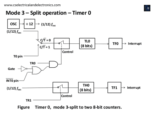
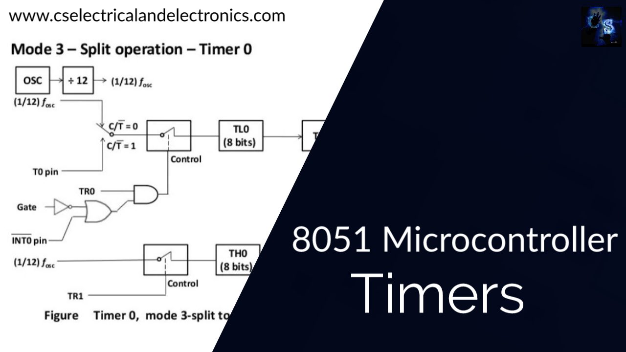
Timer 0 is used as two separate timers of 8-bit TH0 and TL0 where TL0 uses the control bits of Timer 0 (TR0 and TF0) and TH0 uses the control bits of Timer 1(TR1 and TF1).
Note:
- When the timer interrupt occurs, the timer overflow flag will be set. As soon as the processor decides to send the interrupt to ISR, the timer overflow bit is no longer required. Hence timer overflow flag will e cleared.
- Before loading the count, we have to calculate the count because it is an up counter.
- Count to be loaded = Maximum count – desired count + 1.
This was about “8051 Microcontroller Timers”. I hope this article “8051 Microcontroller Timers” may help you all a lot. Thank you for reading.
Also, read:
- 10 Tips To Maintain Battery For Long Life, Battery Maintainance
- 10 Tips To Save Electricity Bills, Save Money By Saving Electricity
- 100 (AI) Artificial Intelligence Applications In The Automotive Industry
- 100 + Electrical Engineering Projects For Students, Engineers
- 1000+ Automotive Interview Questions With Answers
- 1000+ Control System Quiz, Top MCQ On Control System
- 1000+ Electrical Machines Quiz, Top MCQs On Electrical Machines
- 1000+ Electronics Projects For Engineers, Diploma, MTech Students

