Hello guys, welcome back to our blog. Here in this article, we will offer a CAN protocol tutorial, and topics will include the working of the CAN protocol, types of frames in CAN, error detection, CAN synchronization, and the physical layer of CAN.
If you have any electrical, electronics, and computer science doubts, then ask questions. You can also catch me on Instagram – CS Electrical & Electronics.
Also, read:
- Top 20 Interview Questions On Functional Safety In Automotive
- Products Manufactured By Texas Instruments In Various Domains
- Top 12 Microcontroller Manufacturing Companies In The World
Topics:
- Introduction
- Purpose Of CAN Protocol
- Basic CAN Vs Full CAN
- Speed Of CAN Communication Protocol
- Applications Of CAN Protocol
- Speed Of CAN Communication Protocol
- CAN Frames
- The CAN Network For Data Transmission
- Error Handling In CAN Protocol
- CAN Communication
CAN Protocol Tutorial
The multi-master, message broadcast system known as the CAN bus was created by BOSCH and has a maximum signaling rate of 1 megabit per second (bps). CAN do not transfer sizable data blocks point-to-point from node A to node B under the control of a central bus master, unlike a conventional network like USB or Ethernet. A CAN network ensures data integrity at every system node by broadcasting several brief signals to the whole network, such as temperature or RPM.
Introduction:
The CAN protocol is a standard created to enable communication between the microcontroller and other devices without the use of a host computer. The broadcast bus type is what distinguishes the CAN protocol from other communication protocols. Broadcast in this context means that all nodes receive the information.
The node, which can be a sensor, microcontroller, or gateway that enables network communication between computers via USB or ethernet ports, can be a sensor, microcontroller, or gateway. As a message-based protocol, CAN determines priority based on the communication’s identifier, which is carried in the message itself. The CAN network does not require node identification, making it very simple to add or remove a node from the network.
It is an asynchronous, serial half-duplex communication protocol. Given that the CAN network is connected by a two-wire bus, the CAN is a two-wire communication protocol. Twisted pair wires with a 120-ohm characteristic impedance are joined at both ends. It was initially primarily intended for vehicle-to-vehicle communication, but it is currently utilized in a variety of other situations. CAN is a similar technology to KWP 2000 and UDS for onboard diagnostics.
Purpose Of CAN Protocol
As the number of electronic devices increased, a centralized common communication protocol became necessary. For instance, a modern automobile may have more than seven TCU for a variety of subsystems like the dashboard, transmission control, engine control unit, and many others. The communication speed would be very high if every node was connected directly to each other, but the complexity and expense of the lines would also be quite high.
Since a single dashboard in the aforementioned example needs eight connectors, CAN be developed as a centralized solution that only needs two wires, CAN high and CAN low. Using the CAN protocol is a good approach because it prioritizes messages and is adaptable because adding or removing nodes won’t have an impact on the network.
Basic CAN Vs Full CAN
The words “Basic CAN” and “Full CAN” come from CAN’s early years. There once was an Intel 82526 CAN controller that gave the programmer a DPRAM-like interface. Then Philips released the 82C200, a device with limited filtering capabilities and a FIFO (queue) oriented programming model. For whatever reason, the Philips method was referred to as “Basic CAN,” whereas the Intel method was referred to as “Full CAN.”
The phrases “Full CAN” and “Basic CAN” are no longer necessary because the majority of CAN controllers nowadays support both programming paradigms. In fact, using these names can be confusing and should be avoided. Of course, a “Full CAN” controller and a “Basic CAN” controller can communicate with one another. No compatibility issues exist.
Speed Of CAN Communication Protocol
01. Minimum Bus Speed:
Be warned that some bus transceivers won’t let you lower the bit rate below a specific level. For instance, if you use the 82C250 or 82C251, you can go as low as 10 kbit/s without any issues, but if you use the TJA1050, you are only able to go as low as 50 kbit/s. Look over the datasheet.
02. Maximum Bus Speed:
According to the specification, a CAN bus can move data at a maximum speed of 1 Mbit/second. However, some CAN controllers can operate at speeds more than 1Mbit/s and may be taken into consideration for certain applications.
The maximum speed for low-speed CAN (ISO 11898-3) is 125 kbit/s.
Single-wire CAN have a maximum speed of around 50 kbit/s in its regular mode and approximately 100 kbit/s in its high-speed mode, which is used, for example, to program ECUs.
03. Maximum Cable Length
A maximum cable length of around 40 meters (130 feet) can be employed at a speed of 1 Mbit/s. This is due to the arbitration scheme’s requirement that the signal’s wavefront is able to propagate to the node that is the farthest away from the source and return before the bit is sampled. In other words, the length of the cable is constrained by the rate of light. The intergalactic repercussions of increasing the speed of light have been considered, but they were rejected.
Other maximum cable lengths include (approximate values) the following:
500 kbit/s for 100 meters (330 feet), 250 kbit/s for 200 meters (650 feet), 125 kbit/s for 500 meters (1600 feet), and 10 kbit/s for six kilometers (20000 feet)
As galvanic isolation is provided by optocouplers, the maximum bus length is correspondingly reduced. Use quick optocouplers and measure the delay through the device rather than the maximum bit rate stated.
Applications Of CAN Protocol
CAN protocol was initially created to address the communication problem that arises inside cars. Later, however, because of the qualities it provides, it is employed in a number of other fields. The CAN protocol is used in the applications listed below:
- Automotive (passenger vehicles, lorries, buses) (passenger vehicles, trucks, buses)
- Aeronautical and navigational electronics
- Mechanical control and industrial automation
- Escalators and an elevator
- Automated construction
- Medical equipment and devices
- Marine, industrial, and medical
Multilayer Architecture For CAN
The OSI model divides the communication system into seven distinct layers, as is well known. However, there are two layers in the CAN-layered architecture: the physical layer and the data-link layer.
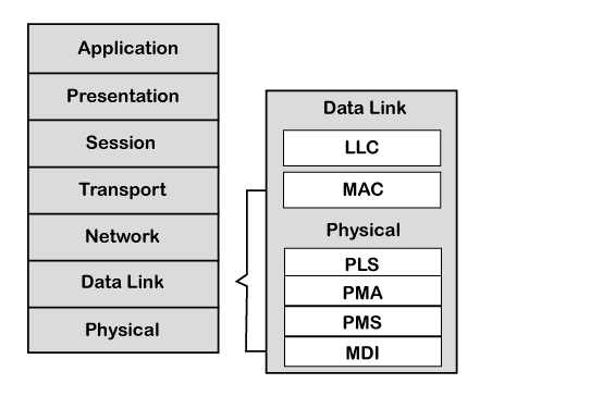
Node-to-node data transport is handled by the data-link layer. You can use it to start and stop the connection. It is also in charge of spotting and fixing any mistakes that might happen at the physical layer. Two sub-layers make up the data-link layer:
Media Access Control, or MAC, is an acronym. It describes how networked devices access the medium. Data encapsulation and decapsulation, error detection, and signaling are provided.
Logical link control is the abbreviation for LLC. Frame acceptance filtering, overload notification, and recovery management are its responsibilities.
Physical layer: The physical layer is in charge of transmitting unprocessed data. It specifies the parameters’ requirements for things like voltage level, timing, data speeds, and connector.
The application, operating system, and network management feature all play a role in the implementation of the CAN controller and CAN transceiver in the software.
CAN Frames
A broadcast type of bus is the CAN bus. As a result, all nodes are able to ‘hear’ all transmissions. It is impossible to transmit a message to a single node; all nodes will always receive all traffic. Local filtering is provided by the CAN hardware, however, so that each node can only respond to the interesting signals.
The maximum utility load for CAN messages is 94 bits. The communications can be considered to be contents-addressed, meaning that their contents determine their address without being explicitly stated.
The different types of CAN frames are:
- Data Frame
- Remote Frame
- Error Frame
- Overload Frame
- Inter-Frame Space
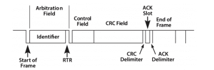
Data Frame
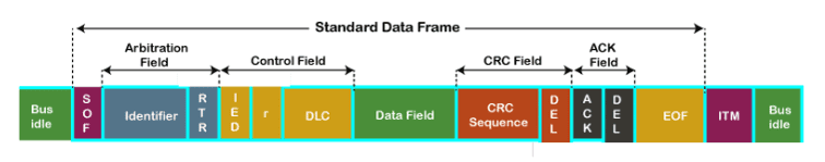
01. The start of frame, or SOF, signifies that a new frame has been inserted into a network. It only has 1 bit.
02. Identifier: A common data format specified by CAN 2.0 An 11-bit message identification is used in a specification for arbitration. In essence, this message identity determines the data frame’s priority.
03. RTR: RTR, or remote transmission request, is a frame type identifier that indicates whether a frame is a data frame or a remote frame. It has one bit.
04. Control field: Its functions can be defined by the user.
- IDE: Identifier extension is indicated by the IDE bit in a control field. The 11-bit standard identifier is defined by a dominant IDE bit, whereas the 29-bit extended identifier is defined by a recessive IDE bit.
- Data Length Code, or DLC, is a term used to describe the length of data in a data field. It has four bits.
- Data field: The data field has a maximum byte size of 8.
05. CRC filed: The data frame also has a 15-bit cyclic redundancy check field that can be used to identify corruption if it happens during transmission. Before transferring the data frame, the sender will compute the CRC. The receiver will then compute the CRC and compare it to the CRC it previously received from the sender. The receiver will produce the error if the CRC does not match.
06. ACK field: This field represents the acknowledgment from the recipient. After receiving all the packets, other protocols send a separate packet for an acknowledgment, while the CAN protocol does not send a separate packet for an acknowledgment.
07. The end of a frame is abbreviated as EOF. It has seven successive recessive bits known as the End of the Frame.
Remote Frame
There are just two significant distinctions between the Remote Frame and the Data Frame:
There is no Data Field and it is clearly identified as a Remote Frame (the RTR bit in the Arbitration Field is recessive).
The Remote Frame’s primary function is to request the transmission of the associated data frame. Node B, if correctly initialized, could send back a data frame with the Arbitration Field set to 234 if, for example, node A transmits a remote frame with the Arbitration Field set to 234.
Request-response bus traffic control can be implemented using Remote Frames. However, the remote frame is rarely utilized in real life. It is also important to note that the behavior described here is not required by the CAN standard. Most CAN controllers can be configured to alert the local CPU in place of automatically responding to a remote frame.
The Remote Frame has one drawback: the Data Length Code needs to be set to the size of the anticipated answer message. If not, the arbitration will not be successful.
It has been said on occasion that the node responding to the empty remote frame is “filling up” the frame by transmitting as soon as the identification is detected. That is not the situation.
Overload Frame
Just to be thorough, the Overload Frame is stated here. Regarding format, it is quite similar to the Error Frame and is transmitted by a node that overworks itself. Due to the ingenuity of modern CAN controllers, the Overload Frame is not frequently employed. In actuality, the now-outdated 82526 is the only controller that will produce Overload Frames.
Error Frame
The Error Frame, to put it simply, is a unique message that deviates from a CAN message’s framing guidelines. It is sent whenever a node notices a fault and prompts all other nodes to do the same, causing them to send Error Frames as well. After that, the transmitter will automatically try to send the message again. A complex set of error counters makes sure that a node cannot continually transmit error frames and disrupt the bus traffic.
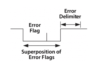
The Error Frame is made up of an Error Flag, which is made up of 6 identical bits and so breaks the bit-stuffing rule, and an Error Delimiter, which is made up of 8 recessive bits. When the other nodes on the bus notice the first error flag, the error delimiter gives them some space in which they can broadcast their own error flags.
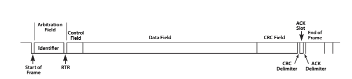
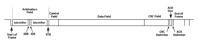
Standard Vs Extended CAN
The Identifier in the Arbitration Field was initially limited to eleven (11) bits per the CAN standard. Later, client demand compelled the standard to be extended. The new format, which is frequently referred to as Extended CAN, permits a minimum of twenty-nine (29) bits in the Identifier. A reserved bit in the Control Field was used to distinguish between the two frame types.
The formal name of the standards
2.0A is the basic version while 2.0B is the enhanced version with all 29-bit Identifiers (or the 11-bit, you can mix them.) A 2.0B node can be “2.0B passive,” which means it will silently discard received extended frames, or “2.0B active,” which means it can transmit and receive longer frames (but see below.) The initial standard and its updates are referred to as 1. x.
Modern CAN controllers are typically 2.0B in design. If a 1. x or 2.0A type controller gets messages with 29 arbitration bits, it will become quite irate. A 2.0B active type controller can both send and receive them, but a 2.0B passive type controller will tolerate them, acknowledge them if they are true, and then discard them.
As long as the controllers implementing 2.0B refrain from sending longer frames, controllers implementing 2.0B and 2.0A (and 1. x) are compatible and may be used on the same bus!
Because Extended CAN message have greater overhead, some argue that Standard CAN is “better” than Extended CAN. This isn’t always the case. Extended CAN actually has a lower overhead than Standard CAN if you employ the Arbitration Field for data transmission.
The CAN Network For Data Transmission
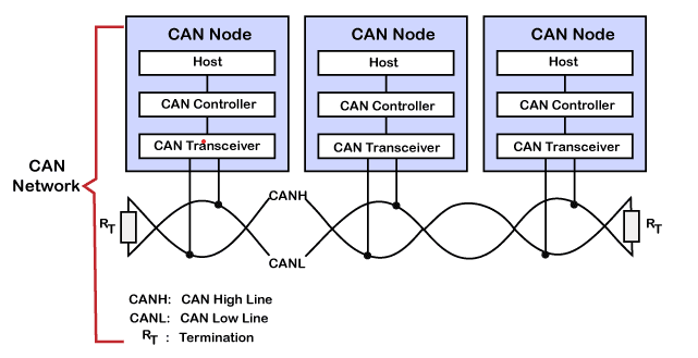
Multiple CAN nodes make up a CAN network. Three CAN nodes were taken into consideration in the scenario above, and they have been given the names node A, node B, and node C. Three components make up a CAN node, and they are as follows:
01. Host: A host is a microprocessor or microcontroller that is running an application to carry out a specified task. A host chooses what a message signifies when it is received and what message it should deliver next.
02. Controlling CAN: The communication functions outlined in the CAN protocol are dealt with by the CAN controller. Additionally, it initiates the transmission or reception of CAN messages.
03. Transceiver for CAN: The CAN transceiver is in charge of sending or receiving data on the CAN bus. It transforms the data signal into a stream of information that the CAN controller can understand that has been gathered from the CAN bus.
An unshielded twisted pair cable is used in the diagram above to send or receive the data. It is also known as the CAN bus, which has two lines: the CAN low line and the CAN high line, sometimes known as CANH and CANL, respectively.
Due to the differential voltage given to these wires, transmission takes place. Due to its surroundings, the CAN requires differential voltage and twisted pair wire. For instance, the motor, ignition system, and many other electronics in a car can corrupt and lose data as a result of noise. The magnetic field is likewise diminished by the twisting of the two wires. At each end of the bus, there is a 120 resistance termination.
Error Handling In CAN Protocol
The CAN protocol includes error handling, which is crucial to the functionality of a CAN system. In order for the transmitter to retransmit an incorrect message, error handling aims to identify faults in messages that emerge on the CAN bus. Every CAN controller along a bus will make an effort to find message problems.
The bus traffic will be destroyed if an error is discovered, as the detecting node will broadcast an Error Flag. If they haven’t already done so, the other nodes will recognize the fault brought on by the Error Flag and respond appropriately, such as discarding the current message.
The Transmit Error Counter and the Receive Error Counter are kept up to date by each node. The incrementing and/or decrementing of these counts is governed by a number of rules. To put it simply, when a transmitter detects a fault, it increases its Transmit Error Counter more quickly than the listening nodes increase their Receive Error Counter.
This is because there’s a good likelihood the transmitter is at blame. The node will first go into “error passive” mode, which means that it won’t actively stop bus traffic when it detects an error, and then “bus off,” which means that it doesn’t take part in the bus traffic at all, when any Error Counter rises above a particular value.
A CAN node can perform error confinement in addition to fault detection using the error counters.
There are no fewer than five different methods of error detection included in the CAN protocol. Three of them operate at the message level, while the other two operate at the bit level.
- Bit surveillance
- Stuffing a bit
- Frame Verify
- Check for Acknowledgement
- Periodic redundancy analysis
Bit Detection: Each transmitter on the CAN bus keeps track of (reads back) the level of the sent signal. A Bit Error is detected if the bit level that was actually read differs from the one that was broadcast. (During the arbitration process, no bit error is reported.)
Stuffing a Bit: A node will add a sixth bit of the opposing level to the outgoing bit stream once it has broadcast five bits in a row of the same level. This extra bit will be taken out by the receivers. This is done to prevent the bus from having too many DC components, but it also offers the receivers a better chance to spot mistakes: if the bus has more than five consecutive bits of the same level, a Stuff Error is signalled.
A frame check/verify: Certain components of the CAN message have a set format, meaning that the standard specifies precisely which levels must happen when. (These components include the CRC Delimiter, ACK Delimiter, End of Frame, and Intermission, although there are additional, unique error checking criteria for that.) A Form Error is raised if a CAN controller notices an invalid value in one of these fixed fields.
Check for Acknowledgement: Regardless of whether they are “interested” in the message’s contents or not, every node on the bus that correctly receives a message is supposed to send a dominant level in the message’s so-called Acknowledgement Slot. Here, a recessive level will be transmitted by the transmitter. An Acknowledgement Error is generated by the transmitter if it is unable to identify a dominant level in the ACK slot.
Periodic redundancy review: A 15-bit Cyclic Redundancy Checksum (CRC) is included in each message, and any node that notices a CRC that differs from the one it calculated itself will indicate an error.
CAN Communication
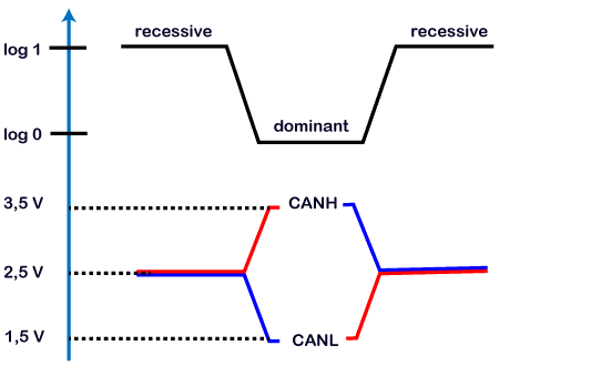
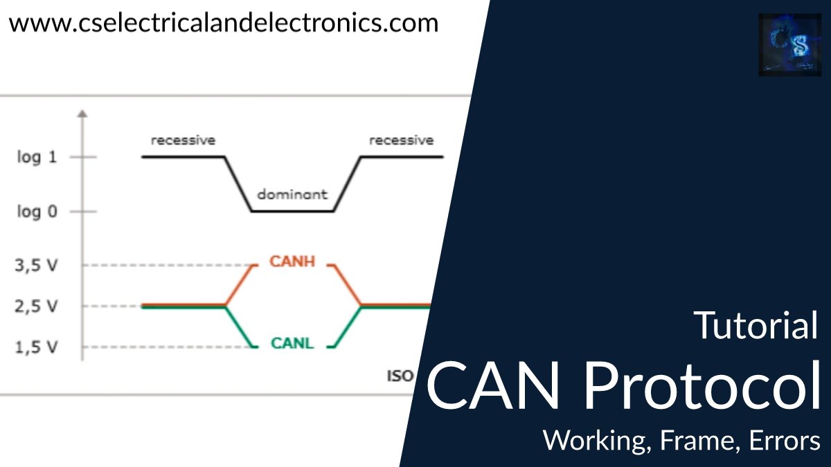
We will examine how 0 and 1 are transferred across the CAN bus using differential voltage. The voltage graph in the previous image displays the voltage levels for CAN low and CAN high. According to the CAN model, logic 0 is dominant and logic 1 is recessive. The actual differential voltage would be zero volts when the CAN high line and CAN low line are applied at 2.5 volts. The CAN transceiver interprets a zero volt on the CAN bus as a recessive or logic 1.
The optimal state of the CAN bus is zero volts. The bus’s rear differential voltage would be 2 volts when the CAN high line was pulled up to 3.5 volts and the CAN low line was pulled down to 1.5 volts. The CAN transceiver interprets it as a dominant bit or logic 0. Any other node would be unable to transition to the recessive state if the bus status hit dominant or logic 0.
The recessive condition is logic 1. Both the CAN high and CAN low should be applied with 2.5V in order to broadcast 1 on the CAN bus. One dominant state is logic 0. CAN high and CAN low should be applied at 3.5 and 1.5 volts, respectively, to transmit 0 on the CAN bus. Recessiveness is the bus’s optimal state. Once a node enters the dominant state, no other node can transfer it back to the recessive state.
This was about “CAN Protocol Tutorial“. I hope this article may help you all a lot. Thank you for reading.
Also, read:
- 10 Free ADAS Projects With Source Code And Documentation – Learn & Build Today
- 100 + Electrical Engineering Projects For Students, Engineers
- 100+ Indian Startups & What They Are Building
- 1000+ Automotive Interview Questions With Answers
- 1000+ Electronics Projects For Engineers, Diploma, MTech Students
- 1000+ MATLAB Simulink Projects For MTech, Engineering Students
- 2000+ Embedded Systems Interview Question Bank
- 2026 Hackathons That Can Change Your Tech Career Forever