Hello guys, welcome back to our blog. In this article, we will discuss the top 16+ electric vehicle projects with MATLAB Simulink files, and EV projects in Simulink and we will also share links so that you can purchase Simulink files.
If you have any doubts related to electrical, electronics, and computer science, then ask questions. You can also catch me on Instagram – CS Electrical & Electronics.
Also, read:
- SoC And SoH Estimation Methods, State Of Charge, State Of Health
- What Is BMS, Battery Management System, Working, Components
- How The Tesla Car Works, Working Of Tesla Car, Autonomous Vehicle
Electric Vehicle Projects
18. Active Cell Balancing Using Fly-back Transformer Of 2 Capacitor Cells In MATLAB Simulink
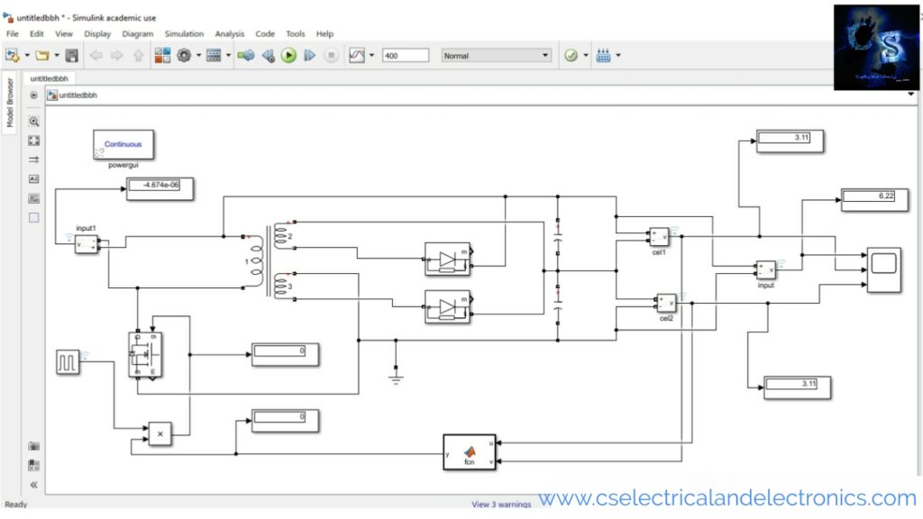
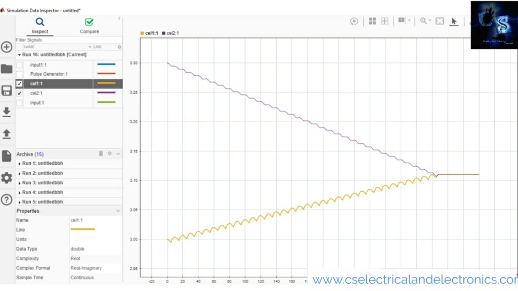
The aim of this project is to make the voltage of each cell equal. The circuit working is simple, initially, the voltage of capacitor 01 is 3, and the voltage of capacitor 02 is 3.3, to make both capacitor voltages the same we are using active cell balancing. The voltage across the two capacitors is 6.3 which is fed to the linear transformer as input. The secondary side has two windings, both carry equal voltage.
When the anode voltage is greater than the cathode then the diode conducts and charges the capacitor. When the anode voltage is less than the cathode then the diode does not conduct and the capacitor only discharges.
Check Here For MATLAB Simulink File
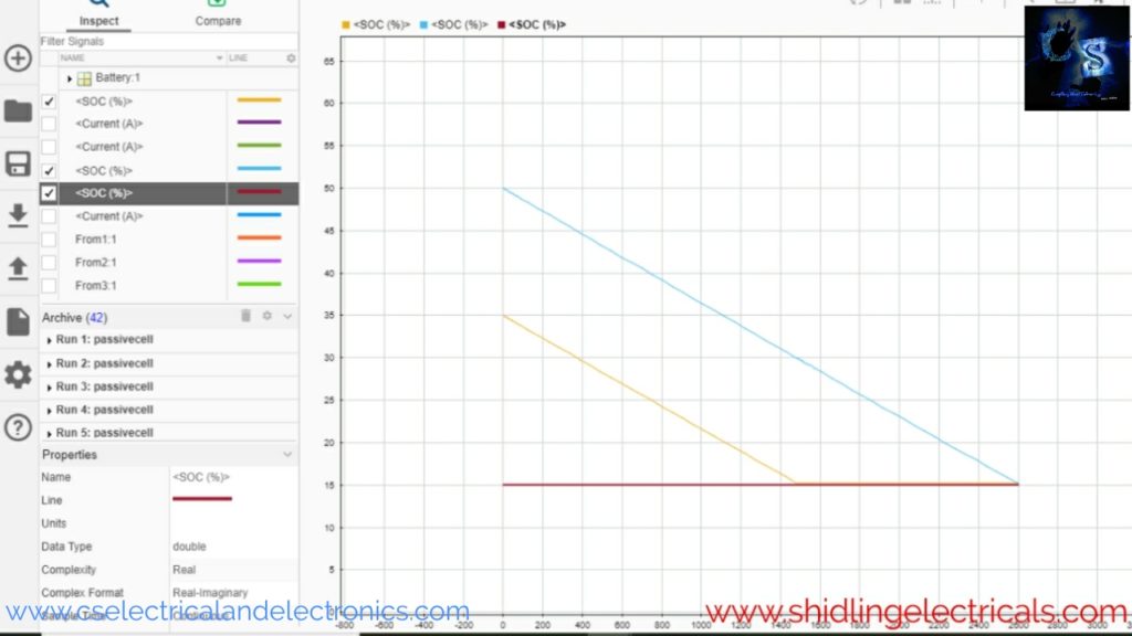
17. Passive Cell Balancing Of Three Lithium-ion Cells For Electric Vehicle Projects
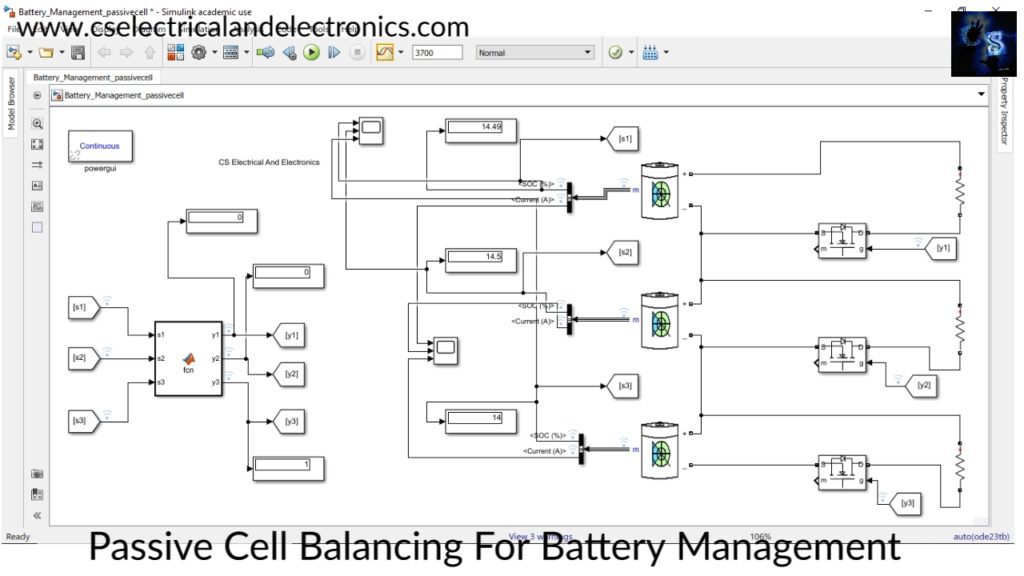
The battery pack is 12 volts and 2.6AHh. It consists of three lithium-ion cells connected in series. Each cell is connected to the load resistance through Mosfet. Passive cell balancing means equalizing the state of charge of each cell by wasting or dissipating energy through a resistor. In passive cell balancing, each cell state of charge value will be brought to the one cell value which has a low state of charge.
Check Here For MATLAB Simulink File
16. Closed Loop Speed Control Of BLDC Motor Using PI Controller
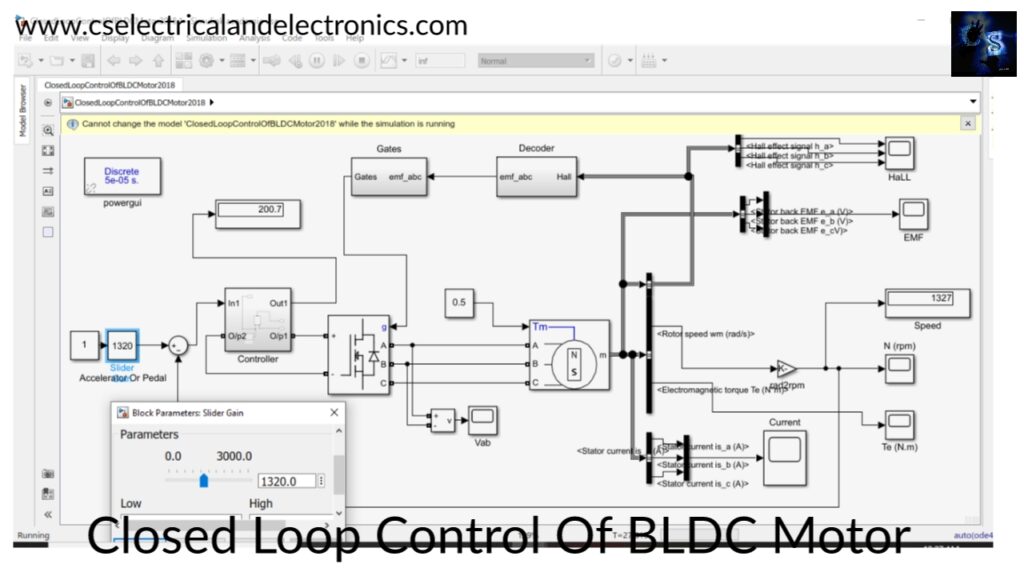
Closed-loop control for a brushless dc motor to work at the precisely entered speed is a method that controls the BLDC (brushless) motor speed according to the user-defined speed. In other terms, this method runs the motor at 25%,50%, or 75% of the total speed when the user sets this percentage of speed in the controller.
In this MATLAB Simulink, the components I am using are PMSM (permanent magnet synchronous motor), inverter, decoder model, controller, and slider gain. I am taking the hall effect signal as feedback to generate a pulse for gates and I am also taking actual speed as feedback to calculate error and adjust the speed of the motor.
Check Here For MATLAB Simulink File
15. Induction Motor Mathematical Modelling In MATLAB Simulink
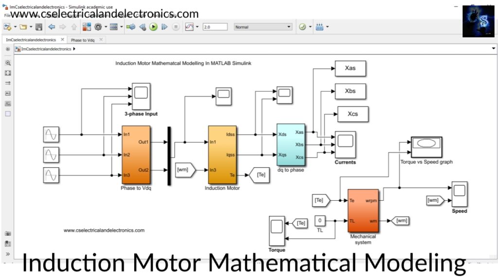
in this design, you will find the MATLAB Simulink file on the mathematical modeling of induction motors. Along with Induction Motor modeling, the model also has Clarke and inverse Clarke transformation blocks. The Clarke transformation block is used to convert a three-phase quantity into a two-phase quantity. The inverse Clarke transformation block is used to convert two-phase quantity into three-phase quantity.
Check Here For MATLAB Simulink File
14. Battery Mathematical Modelling In MATLAB Simulink For Electric Vehicle Projects
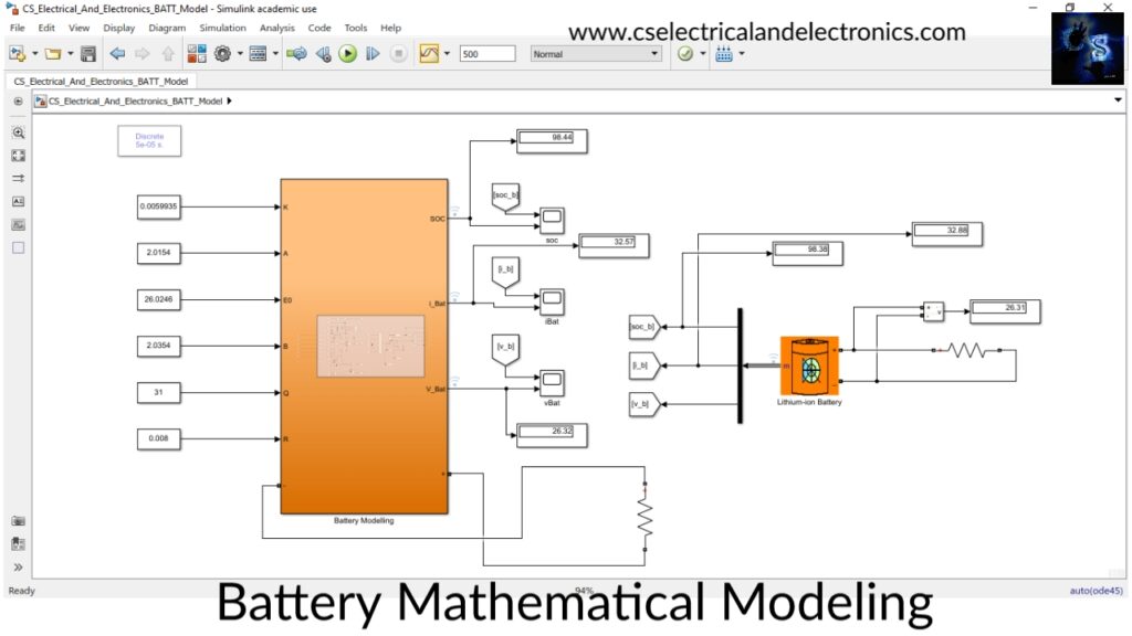
The requirement of a battery dynamic model
- For evaluating the suitability of battery in any application.
- To analyze performance under various operating conditions.
The battery dynamic model forms an integral part of analyzing and prototyping EVs for the efficient design of battery management systems.
Check Here For MATLAB Simulink File
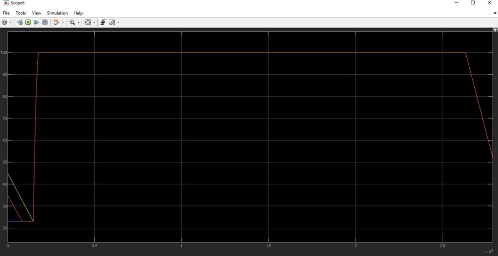
13. BMS Using Passive Cell Balancing, Efficient Charging, Discharging, Fault Protection
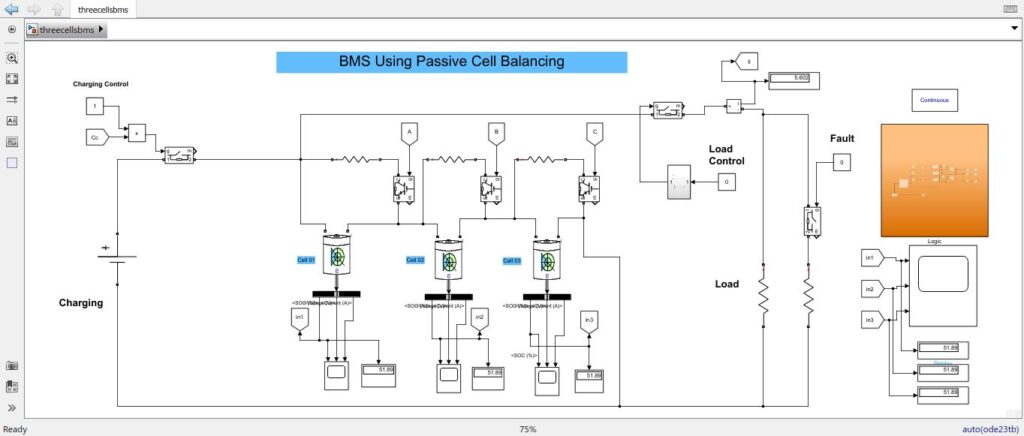
BMS or Battery Management System plays a very important role in electric vehicles. To monitor and maintain the battery pack for proper usage, a BMS is needed. The main functions of BMS are
- Cell balancing: equalizing the Soc and voltage of each cell
- Protecting the battery pack from overcurrent, overvoltage, & under-voltage condition
- Monitoring the temperature, & isolating the BMS if the temperature exceeds
- Monitoring current, voltage, SoC (state of charge), SoH (state of health)
- Efficient charging & discharging
Check Here For MATLAB Simulink File
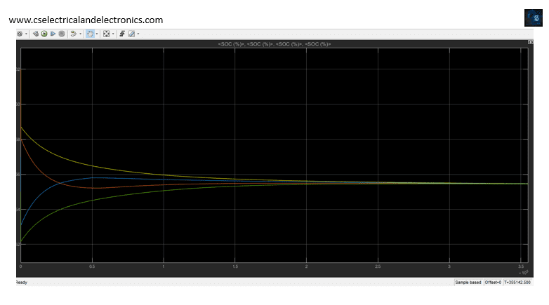
12. Capacitor Based Active Cell Balancing Of Four(4) Lithium-Ion Cells
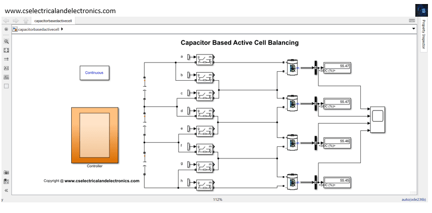
The active cell balancing methods remove the charges from higher energy cell(s) and deliver them to lower energy cell(s). It has different topologies according to the active element used for storing the energy such as a capacitor and/or inductive component as well as the energy converters. Not a lot of cell balancing researches illustrates the switched capacitor cell balancing topologies such that it may be due to the switched capacitor methods having a long equalization time, but on the contrary, they have a simple control strategy and high efficiency.
Check Here For MATLAB Simulink File
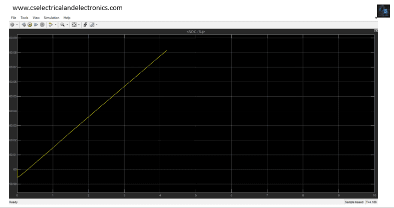
11. Wireless Charging Station For E-bike, 230 V AV Supply / 48 V DC, 25 Ah Battery Pack For Electric Vehicle Projects
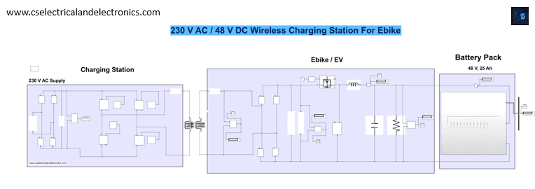
Research is focused on renewable energy sources and energy-saving to reduce fossil fuel consumption and emission. Moreover, to reduce air pollution electric vehicles are widely promoted. In this field, important issues are diagnostic systems to improve power train reliability. For automotive applications, inductive power transfer-based battery charging is gaining great popularity over wired-based charging.
Inductive Power Transfer (IPT), based on magnetic coupling, can be exploited to address energy from the electric mains to the electric load. The magnetic coupling occurs by means of two coil windings: the power transmitter winding, connected to the mains, is the primary inductor; the power receiver winding, connected to the load, is the secondary inductor.
IPT-based battery charging for a vast range of power targets is a widely researched issue. Consumer handheld devices and electric vehicles represent some of these applications. For all cases, covering the range from Watt to kWatt power levels, the most important advantages brought by IPT-based wireless battery charging are safety and comfort.
Check Here For MATLAB Simulink File
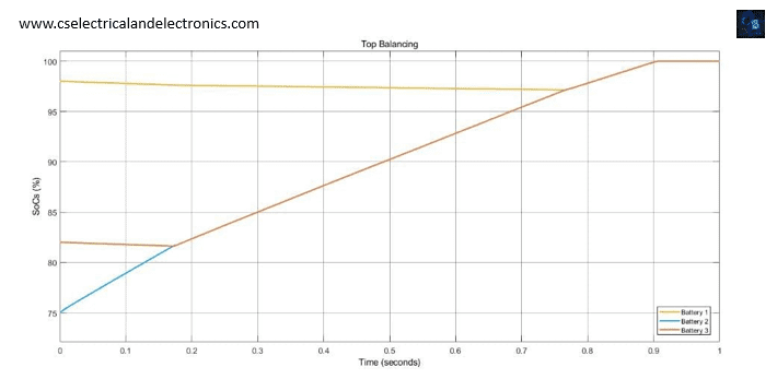
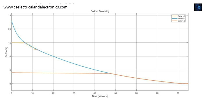
10. 3 Lithium-Ion Cells Top & Bottom Cell Balancing In MATLAB Simulink For Electric Vehicle Projects
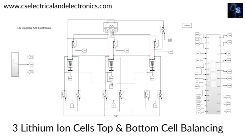
Top Balancing (Charging Mode): During charging a difference in the SoC values between B3 and the other batteries is observed, which becomes prominent when batteries are close to their CVL. It is easily noticeable that B3 has the highest SoC. To equalize the SoCs, the balancing topology transfers energy from B3 to the other batteries. As a result, batteries B1 and B2 are charged not only by the voltage source but also by the energy received from B3. Thus, the energy of B3 decreases. This process continues till all the batteries have the same SoC, post which the normal charging process continues.
Bottom Balancing (Discharging Mode): Similar to the charging mode, during discharging a difference in the SoC values between B3 and the other batteries is observed, which becomes prominent when batteries are close to their DVL. It is easily noticeable that B3 has the lowest SoC. To equalize the SoCs, the balancing topology transfers energy from all the batteries to B3. As a result, batteries B1 and B2 discharge faster. Since B3 receives energy from the battery pack, the net discharge rate is slow. Thus, the energy of batteries B1 and B2 decreases more quicker than B3. This process continues till all the batteries have the same SoC, post which the normal discharging process continues.
Check Here For MATLAB Simulink File
09. Mathematical Modelling On VSI Fed PMSM Using DTC Method For Electric Vehicle Projects
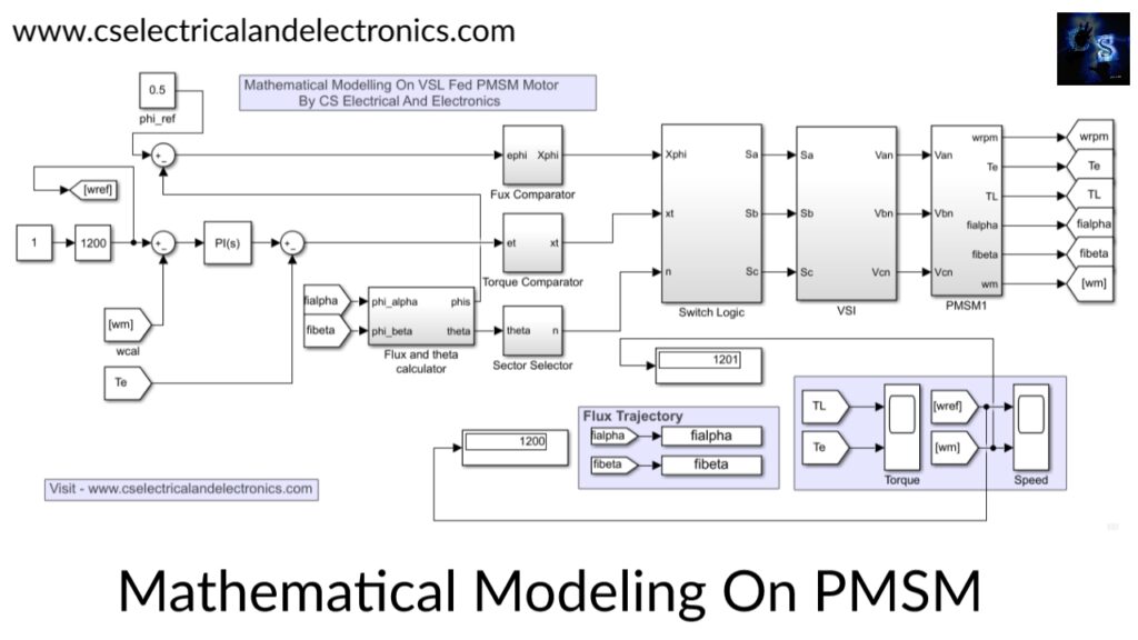
The aim of this project is to develop a mathematical model of PMSM and implement direct torque control of PMSM and evaluate the performance of PSMS motor drive. The stator of the PMSM comprises balanced three-phase winding similar to the wound rotor synchronous motor. The mathematical model of PMSM is derived from that of a wound rotor machine under the assumption that the armature emf is induced by the permanent magnets in place of dc excitation.
Three signals affect the control action in a DTC system. They are namely
1. Torque
2. The amplitude of the stator flux linkage
3. Angle of the resultant flux vector
The estimator obtains the torque and flux signal. Regulation of these two signals is done with the help of two hysteresis controllers. The rotor position estimator and the hysteresis controller give output signals to the switching table who in turn selects switching of the inverter legs and applies a set of voltage vectors across the motor terminals.
Check Here For MATLAB Simulink File
08. Vehicle-To-Grid Technology in a Micro-grid Using DC Fast Charging Architecture
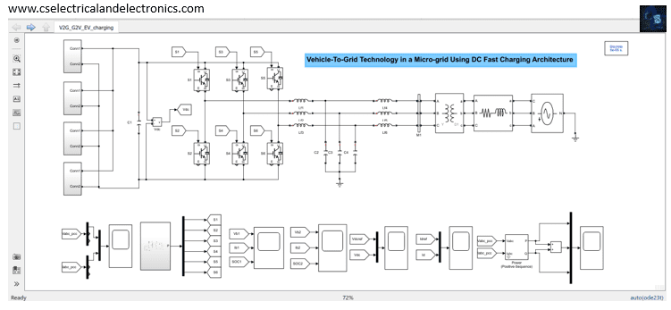
Electric Vehicle (EV) batteries can be utilized as potential energy storage devices in micro-grids. They can help in micro-grid energy management by storing energy when there is a surplus (Grid-To-Vehicle, G2V) and supplying energy back to the grid (Vehicle-To-Grid, V2G) when there is demand for it. Proper infrastructure and control systems have to be developed in order to realize this concept. Architecture for implementing a V2G-G2V system in a micro-grid using level-3 fast charging of EVs is presented in this paper.
A micro-grid test system is modeled which has a dc fast charging station for interfacing the EVs. Simulation studies are carried out to demonstrate V2G-G2V power transfer. Test results show active power regulation in the microgrid by EV batteries through G2V-V2G modes of operation. The charging station design ensures minimal harmonic distortion of grid-injected current and the controller gives a good dynamic performance in terms of dc bus voltage stability.
Check Here For MATLAB Simulink File
07. Three-Phase 5-Switch 7-Level Cascaded Multilevel Inverter For Electric Vehicle Projects
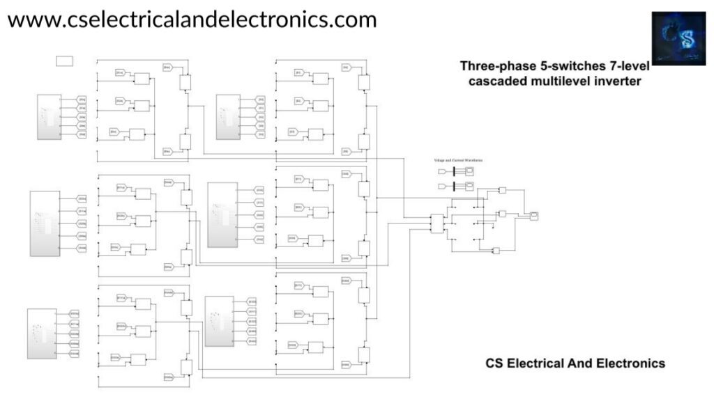
In this design, a new 5-switch seven-position DC-AC inverter is proposed. The proposed cascaded multilevel inverter uses a reduced number of switches as compared to the switches used in the conventional multilevel inverter. The inverter has been designed to induce a 7-position AC affair using 5 switches.
The voltage stress on each of the switches as well as the switching losses are planted to be less, minimized common-mode voltage (CMV) position, and reduced total harmonious deformation. The proposed 7- position inverter topology has four dc sources, which are amped through the PV system. The proposed inverter is controlled with help of multicarrier sinusoidal palpitation range modulation (MCSPWM). The simulation results were vindicated using Matlab Simulink.
Check Here For MATLAB Simulink File
Check Here For MATLAB Simulink File
06. Electric Vehicle Dynamics For Rickshaw (Three Wheels), SoC Estimation, Distance Travelled, Drive Cycle
To advance the safety analysis and reduction costs, the solutions will be based on flexible user-friendly interfaces and specialized software tools. This work presents exhaustive modeling of EV dynamics, powertrain, and energy storage/conversion.
The simulation model is useful for both electrical component sizing at a designed time and onboard diagnostic to check component aging. The aim is to model the transient response of the system while preserving the simplicity and feasibility of the simulation.
The design of an EV requires, among others, the development and optimization of a completely electric powertrain system, including the longitudinal car, battery system components, power electronics, electric machine, and control system.
Check Here For MATLAB Simulink File
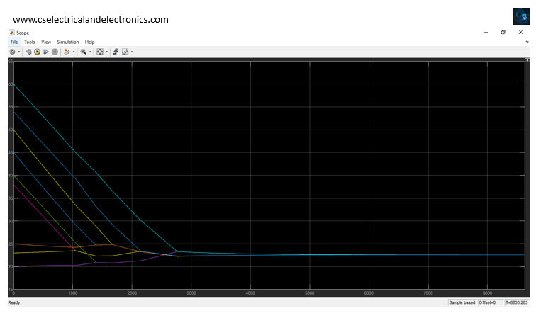
05. Modular Cell Balancing, 3 Module, 3 Cells In Each Module For Electric Vehicle Projects
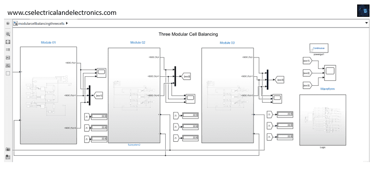
This simulation is needed when you want to balance cells in different battery packs. The above simulation consists of 3 modules and each module will have 3 cells connected in series.
Balancing is only necessary for packs that contain more than one cell in a series. Parallel cells will naturally balance since they are directly connected to each other, but groups of parallel wired cells, wired in series (parallel-series wiring) must be balanced between cell groups.
Cell balancing is a technique that improves battery life by maximizing the capacity of a battery pack with multiple cells in series, ensuring that all of its energy is available for use.
Check Here For MATLAB Simulink File
04. Active Cell Balancing To Balance Ten (10) Cells MATLAB Simulink File
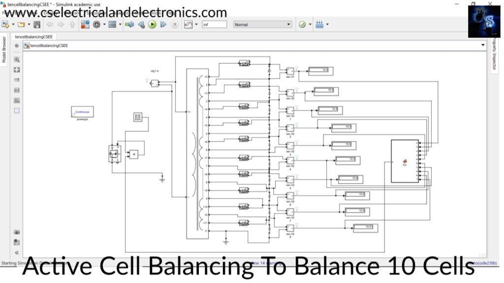
Here in this model, we are using 10 cells and the initial voltage of each cell is different when the active cell balancing technic has been applied the voltage of each cell will be equal to the average of all initial voltages present in the cells.
Check Here For MATLAB Simulink File
03. ANN (Artificial Neural Network) Based Speed Control Of Permanent Magnet DC Motor
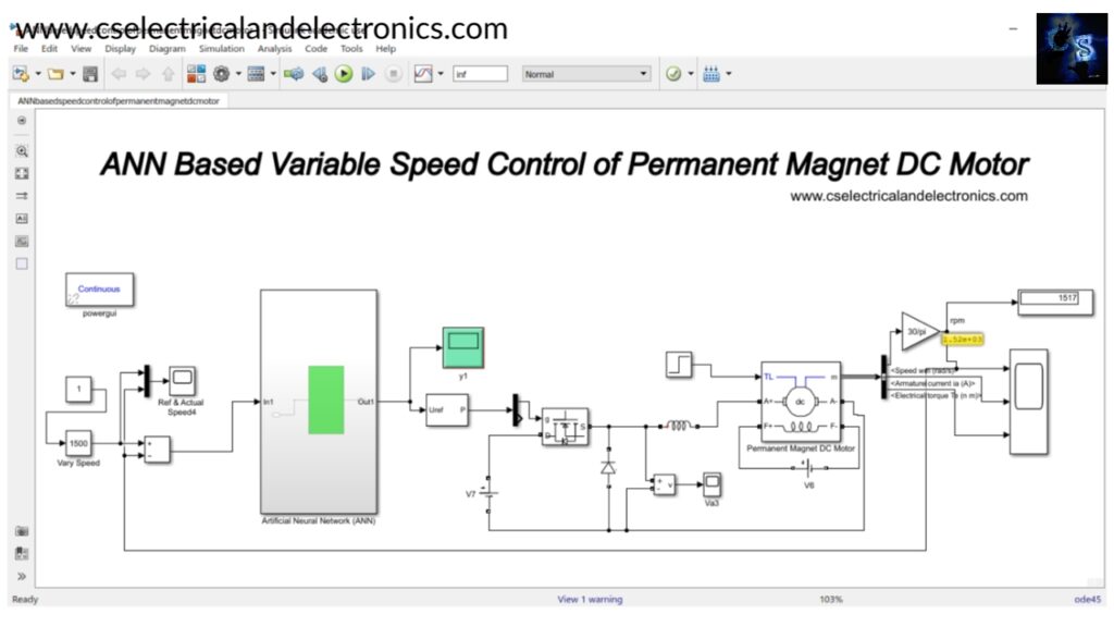
This project is done to study Artificial Neural networks controlling the speed of the DC motor. Overall the controller performs great on controlling the speed of the DC motor in the simulation and experimental part. ANN controller reacts faster on adjusting the speed of the DC motor to achieve the desired speed. Using ANN, there is no need to calculate the motor parameters of the motor when designing the control system. ANN-based control has reduced the settling time to 0.3 sec.
Hence the overall study indicates an appreciable advantage of artificial neural network control over the conventional control methods. ANN control can be used for the control mechanism of machines with complicated load patterns.
Check Here For MATLAB Simulink File
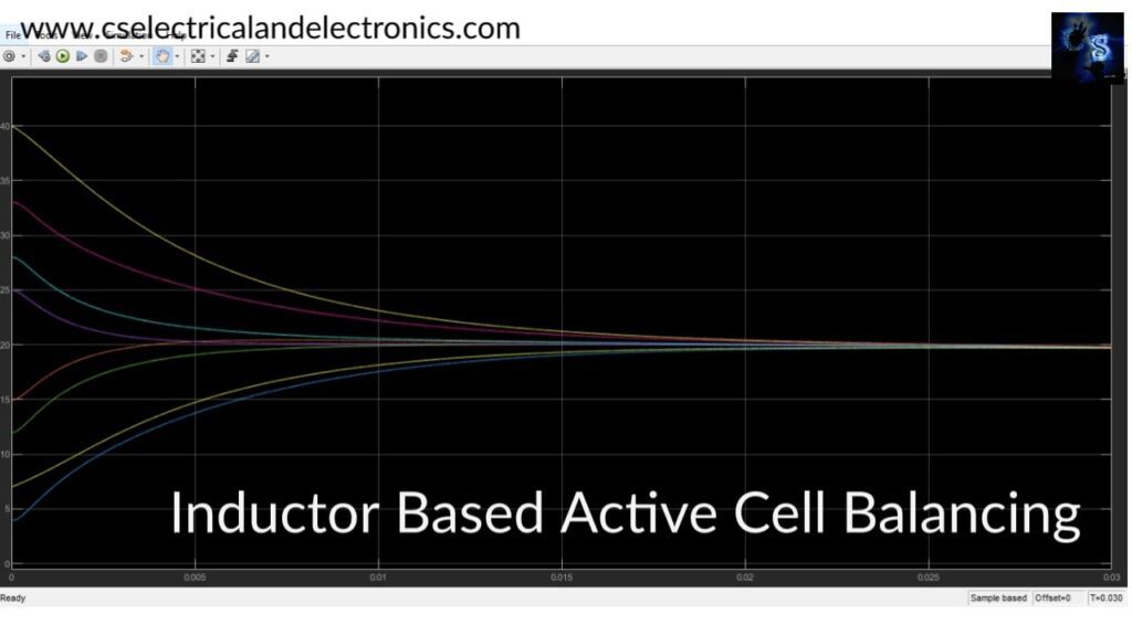
02. Inductor Based 8 Cells (Capacitor) Active Cell Balancing For Electric Vehicle Projects
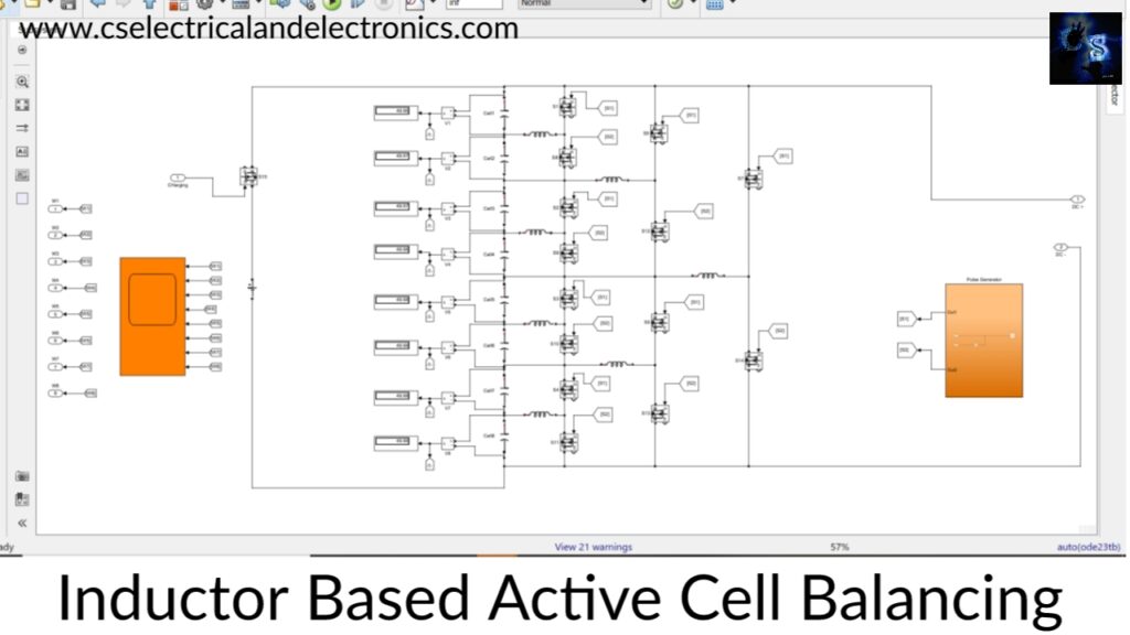
This model presents the concept of an active cell balancing mechanism for Lithium-Ion (Li-ion) batteries for Electrical Vehicles (EV) based on the inductor balancing method.
It equalizes eight cells in a series. Voltage differences always exist between cells, therefore a battery management system (BMS) is required to ensure that all cells are equally charged or discharged and it increases the life cycle of the battery.
An equalizing method is essential to achieve the best performance. A number of cell balancing methods have been presented. Among them, inductor-based balancing is faster compared to other methods such as Switched-Capacitor Converter (SCC).
The problem of the conventional inductor-based balancing method occurs when the energy transfers from the first cell to the last one and causes long time equalization because the energy transfer is cell by cell.
Check Here For MATLAB Simulink File
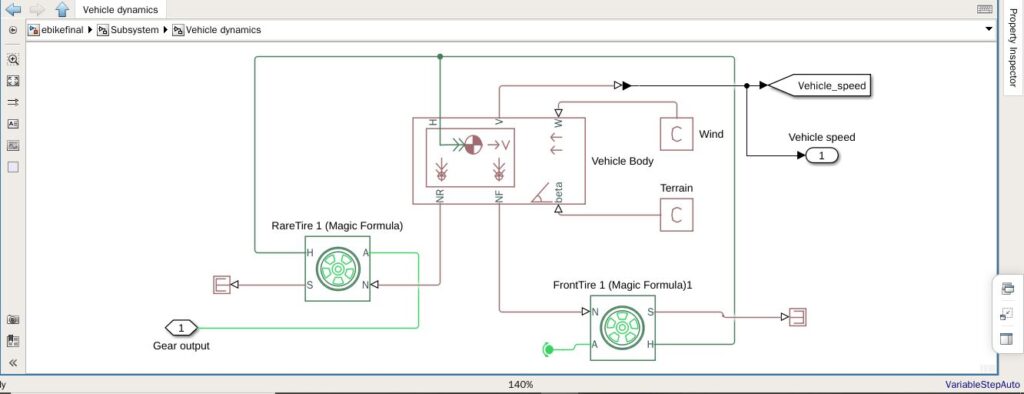
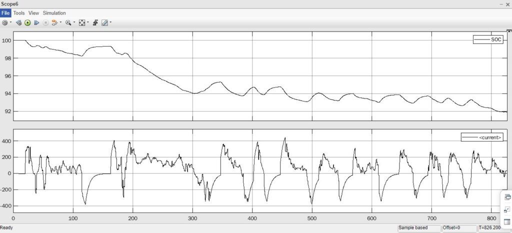
01. Ebike Dynamics, SoC Estimation, Regenerative Braking, Drive Cycle
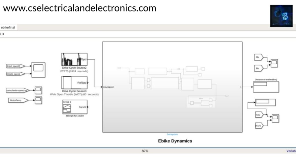
Electric bikes (e-bikes) are two-wheeled vehicles powered by electric motors and batteries. Some styles resemble bicycles, while others are larger and have the appearance of gasoline scooters; all possess nearly identical underlying technology.
The e-bikes typically have top operating speeds of around 30 km/h and weights ranging from 30 to 80 kg. Because of their lightweight and efficient drive train. To advance the safety analysis and reduction costs, the solutions will be based on flexible user-friendly interfaces and specialized software tools. This work presents exhaustive modeling of Ebike dynamics, powertrain, and energy storage/conversion.
Check Here For MATLAB Simulink File
This was about “Electric Vehicle Projects“. I hope this article “Electric Vehicle Projects” may help you all a lot. Thank you for reading.
Also, read:
- 10 Free ADAS Projects With Source Code And Documentation – Learn & Build Today
- 100 + Electrical Engineering Projects For Students, Engineers
- 100+ C Programming Projects With Source Code, Coding Projects Ideas
- 1000+ Electronics Projects For Engineers, Diploma, MTech Students
- 1000+ MATLAB Simulink Projects For MTech, Engineering Students
- 500+ Matlab Simulink Projects Ideas For Engineers, MTech, Diploma
- AI And ML Projects For Electronics Engineers
- Blockchain Projects For Computer Science Engineers