Hello guys, welcome back to our blog. Here in this article, we will discuss the top 20 tools to design a schematic of an electronic circuit or schematic design tools, which tool will be best, and their features.
If you have any electrical, electronics, and computer science doubts, then ask questions. You can also catch me on Instagram – CS Electrical & Electronics.
Also, read:
- What Is ADC, Working Of ADC, Analog To Digital converter
- CAN Protocol Tutorial, Working, Frames, Interview Q’s, Errors
- Top 20 Technologies In Railways, Railway Technology
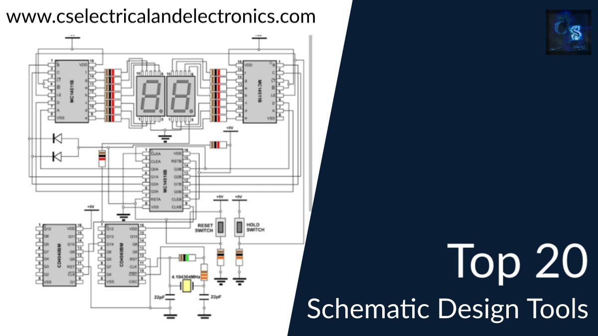
Top 20 Tools To Design A Schematic
Since 1981, when commercial EDA was formally introduced, the EDA industry has generated a variety of design software. PCBs, commonly referred to as printed circuit boards, are the building blocks of any hardware-based device. Engineers typically designed electronic circuitry and integrated circuits by hand or through other manual processes prior to the invention of EDA software.
Anyone, from hobbyists to small businesses, can find new opportunities by designing and creating PCBs. PCBs provide more durable, dependable, and compact final solutions for the numerous projects that fail to move beyond a breadboard. Additionally, PCBs are no longer just green rectangles for those who want to get creative. They may have any color or shape, be transparent, or even be malleable.
There are many different PCB programs available; some are free and some are paid. Making a decision from among the many tens of available pieces of software can be difficult. It is always advisable to use some of the most recent tools with available support and community when choosing a design package.
Some of the best and most well-liked tools in the EDA sector are typically not free. Nevertheless, a few potent free ones are still available. In this article, I’ll list some of the best free PCB design tools you can find for creating printed circuit board layouts in the hopes that you can choose from this list.
20. ZenitPCB
is a great PCB layout design tool for making expert printed circuit boards ( PCB ). It is a versatile, simple-to-use CAD program that enables you to quickly complete your tasks. Using ZenitPCB Layout, a project may be started using either the schematic capture or the layout itself.
19. KiCad
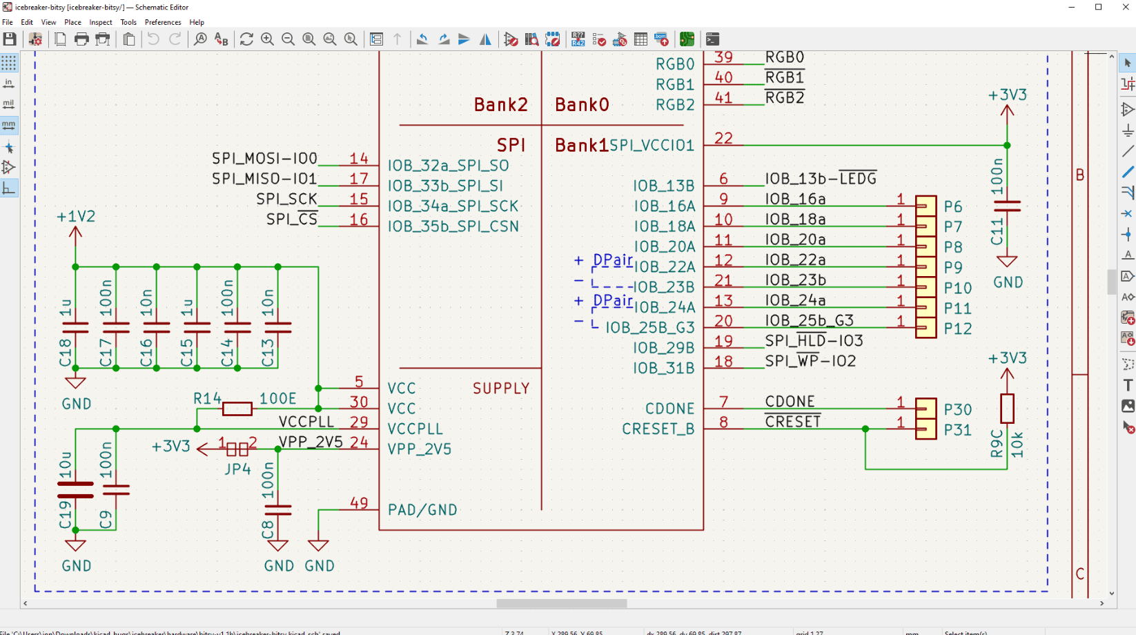
One of the most well-known free PCB and electronics design programs is KiCad. It was first developed about 30 years ago, and as of version 6, it has undergone considerable upgrades over the past year, including significant UI and editor improvements, new design management tools, and improved plug-in compatibility. KiCad has a vibrant community and holds a well-attended annual conference. It is supported by well-known organizations like the Raspberry Pi Foundation, Arduino, and CERN (European Organization for Nuclear Research).
The open-source program has a robust feature set that can be used by both novices and experts. KiCad incorporates circuit simulation (Ngspice), supports Git for version control, and collaborates with FreeCAD for other generic 3D designs in addition to the standard circuit schematic design, PCB layout tools, and 3D visualization. Additionally, a growing number of plug-ins offer extension opportunities using Python for everything from RF design to PCB art.
18. Eagle
Rudolf Hofer and Klaus-Peter Schmidiger developed the PCB design software EAGLE at the German CadSoft Computer GmbH in 1988. In 2009, Farnell bought the business, and in 2016, Autodesk, a venerable software giant with annual sales of over 2 billion euros, bought it. Easily Applicable Graphical Layout Editor is referred to as EAGLE.
Specifications and features
- Editing a diagram (connected to the library, electric rules, generation of an interconnection list)
- Notation of modifications between the PCB and the diagram
- Picture hierarchy
- Schematic of the layout with advanced features
EAGLE has the benefit of being a PCB design software powerhouse. It has a sizable community that posts tutorials online for a fair $500/year price. It may be used with Linux or Mac OS X and includes a sizable component library.
17. Fritzing
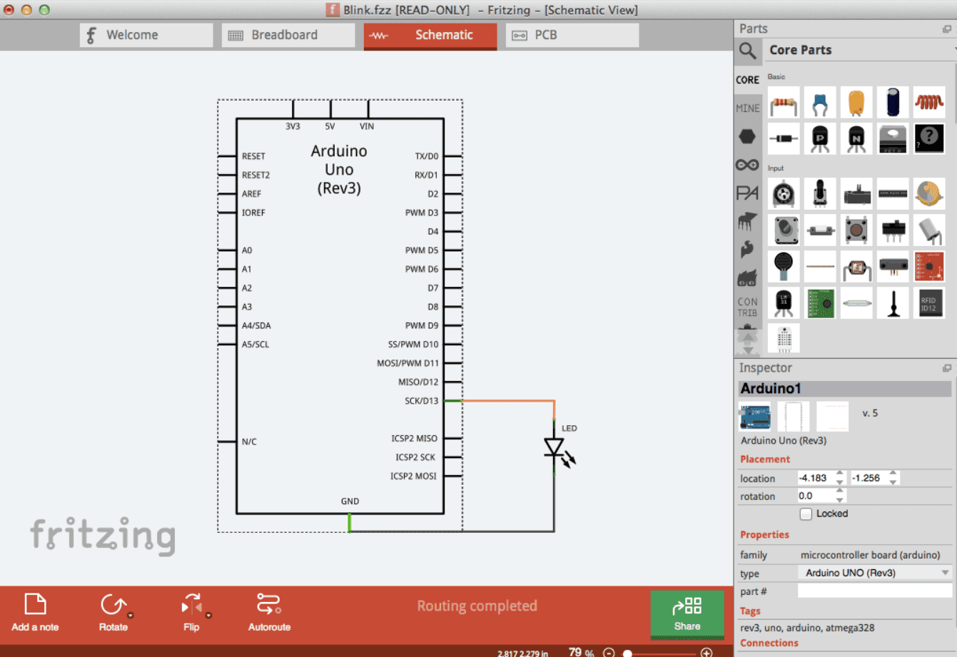
Fritzing is an open-source electronics education tool, similar to KiCAD. With its demonstrations of Arduino and user-friendly platform, Fritzing quickly gained popularity. For designing a PCB layout for your board, Fritzing offers a schematic view, breadboard layout, and PCB view. Fritzing is a popular option among amateurs thanks to its rich user interface and expanding community. It is available for Windows, Linux, and Mac.
16. TinyCAD
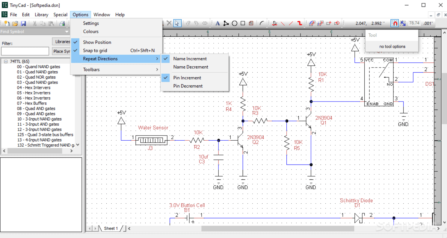
Is a tool for creating circuit diagrams. Complete symbol libraries are included to get you going right away. You can use TinyCAD to publish your designs in addition to just printing them out by copying and pasting them into a Word document or saving them as a PNG bitmap for the web.
15. EasyEDA
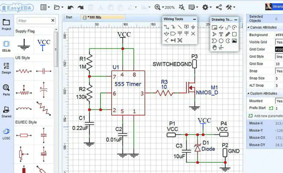
With support from one of China’s top electrical component vendors, EasyEDA is a relatively new addition. The original and classic version, which was created out of a need for software that doesn’t need Windows, is online and useable by any device with a compatible browser (where Chrome or Firefox are preferred).
Simple visualization tools, simulation, PCB layout, and schematic capture are all included in the functionality. Due to its cloud-based architecture, it is simple to use while on the go and to collaborate with others. Additionally, EasyEDA has embedded direct library links to LCSC for components and JLCPCB for reasonably priced production services, producing industry-standard files that can be used with any PCB maker.
14. Altium
Australia’s Protel Systems was established in 1985, however, the business changed its name to Altium in 2001. It is currently American and a leader in PCB modeling software. The company welcomes 6000 new customers annually and plans to reach a $200 million turnover in 2020.
Specifications and features
- Diagrams, layout routing, documentation, and simulation environments
- Design for Manufacturing (DFM) is a process that ensures the usability, dependability, and simplicity of your PCB designs.
- Utilizing strong conversion tools for simple data movement
- Design in 3D flex-rigid
- Circuit board design
- Diagram format
- The output of production files
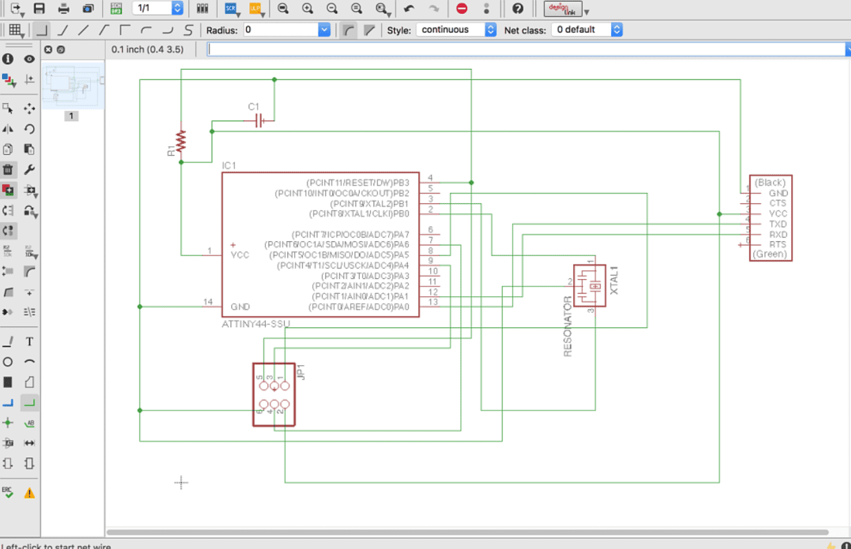
13. DesignSpark PCB
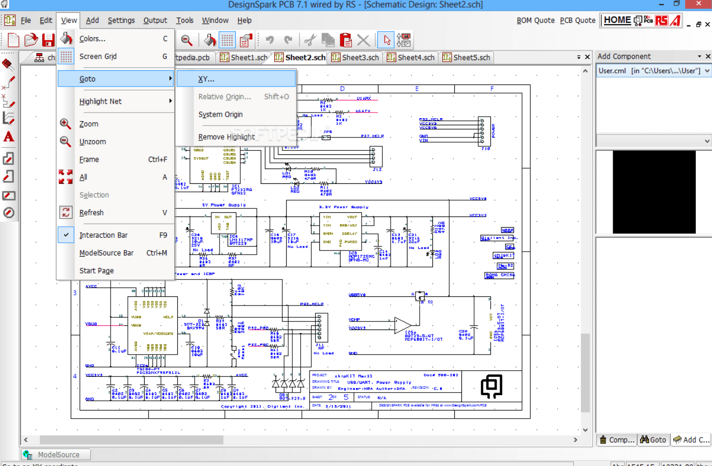
One of the EDA tools to test out is DesignSpark PCB, which has a schematics capture and PCB layout tool in addition to an environment that is debatably simple to learn. It is open source, has great schematic capture capabilities, is a PCB designer that allows you to design an unlimited number of PCB layers, the ability to create parts and libraries, 3D views, and many other features. Only Windows users can use DesignSpark PCB.
12. Osmond PCB
Is a versatile design tool for printed circuit boards. It is Macintosh-based. Its many features include support for both through-hole and surface mount parts, virtually unlimited board sizes, a number of board layers, and more.
11. Upverter
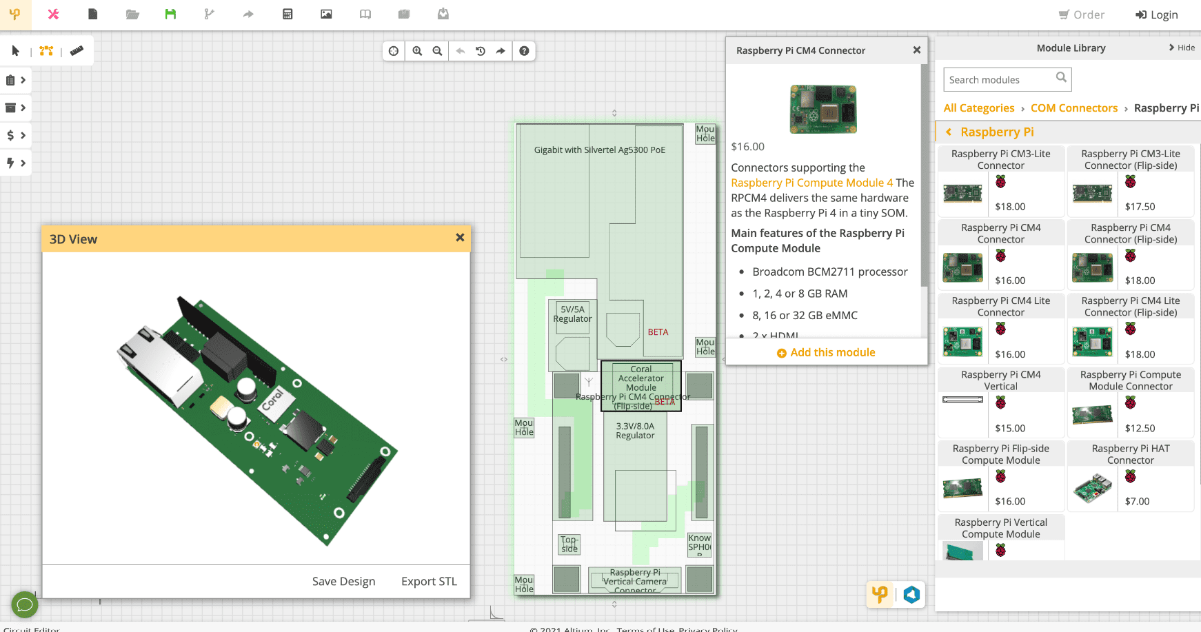
A leader in professional EDA solutions and PCB design, Altium offers Upverter online. It was developed with the straightforward goal of enabling users to make electronics whenever and wherever they wish and to share them with like-minded people.
The program is user-friendly and combines common circuit design, PCB layout, and 3D visualization features with straightforward cloud-based collaboration. It allows users to simply add their own parts in addition to having a library of components that is kept up to date.
10. Cadstar
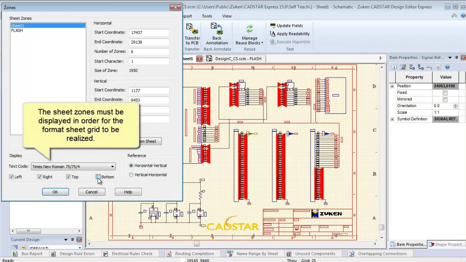
Another design tool for multi-layer PCBs, from the simplest to the most complicated, is Cadstar. This software was created by Rascal-Redac and later joined the Zuken portfolio, a Japanese multinational that was established in Yokohama in 1976 and was a pioneer in the development of electronics CAD software.
The entire printed circuit board design process, from conceptualization through production, is handled by Cadstar.
Specifications and features
- Routing and topology for printed circuits
- The capture of a diagram
- Using STEP or ACIS, mechanical integration for data transmission
- Analyses, tests, and measurements (reliability, signal integrity)
- Library Administration
- review of the design for project managers
09. ExpressPCB Plus
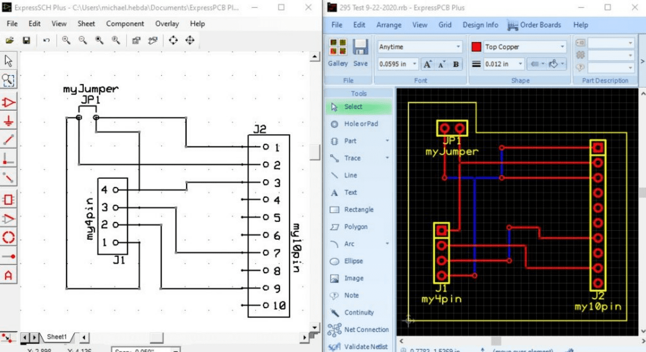
An EDA program called ExpressPCB Plus is used to create and design electronic circuitry. ExpressPCB Plus and ExpressSCH Classic for circuit board layout are both included. You can order your PCB board for fabrication inside ExpressPCB Plus and view the instant quotes for your PCB board there as well. Use of ExpressPCB is possible on Windows, Linux, and Mac.
08. BSch3V
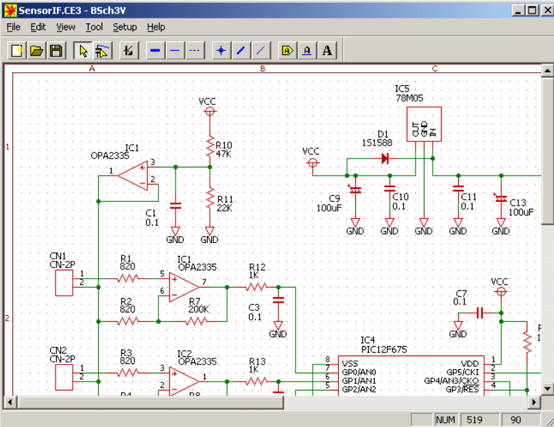
is a Windows program for schematic capture. The abbreviation “BSch” stands for “Basic Schematic.” To make the operation simpler, it only has the bare minimum of features.
07. CircuitMaker
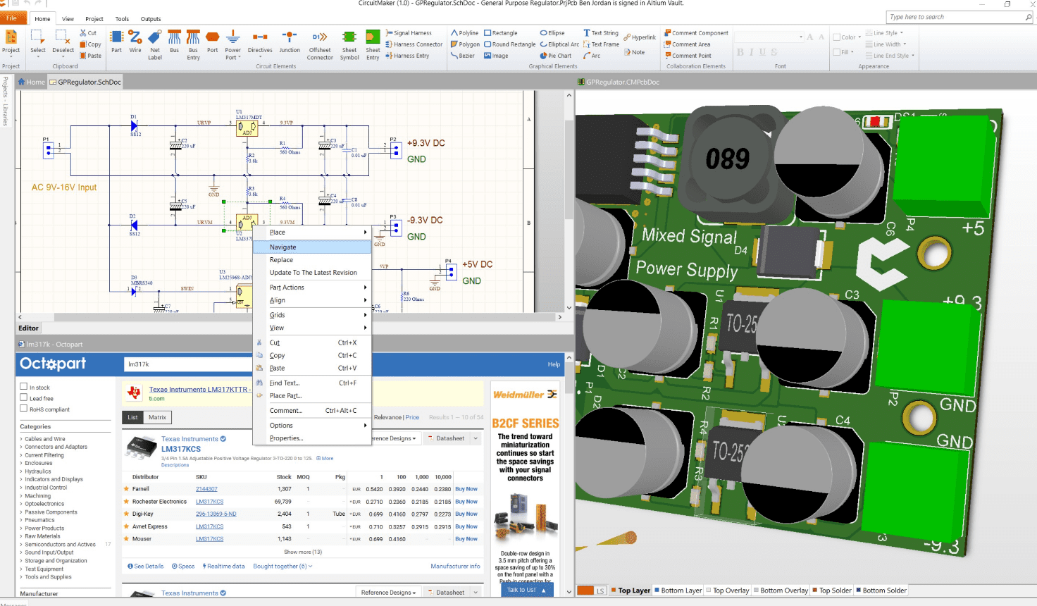
Another free product from Altium is CircuitMaker, which sits between its online Upverter and its professional tools. Its primary point of differentiation is to present itself as a “community for creative electronics” rather than merely a toolkit. The maker, open-source hardware, and nonprofit sectors are its target audiences.
CircuitMaker offers various capabilities typically available exclusively in professional tools, in addition to the standard design and layout functionality, including complex routing, native 3D visualization, design rule checking, and a substantial component library.
The client software interfaces with central databases that provide connections to other community members, information centers on subjects ranging from education to Arduino, and examples of completed projects.
06. Sprint-Layout
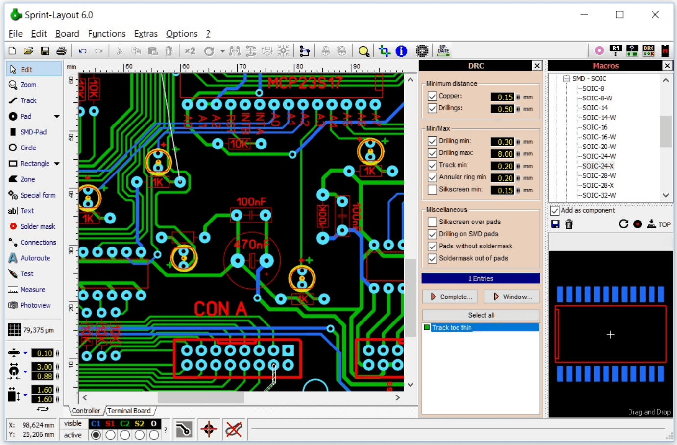
Software for designing electronic prototypes called Sprint-Layout is offered by Abacom. Sprint-Layout has become a necessity for electronics engineers thanks to its excellent ergonomics, professional software-quality capabilities, and extremely affordable price.
Specifications and features
- Automatic two-sided PCB routing
- Library of conventional and CMS components that is very large.
- Development of new components
- Creation of Excellon and Gerber files
- Anti-aliasing \sDesign-Rule-Check
05. gEDA
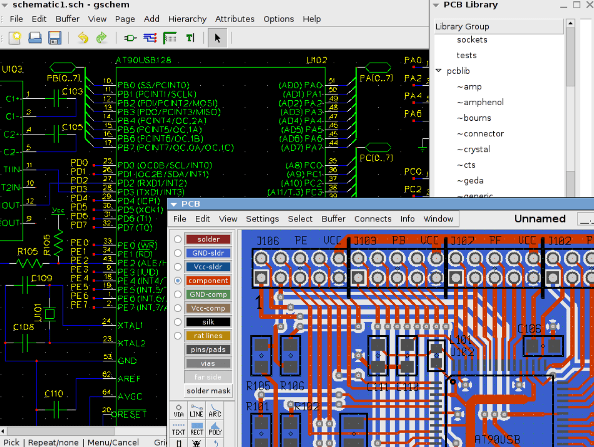
Has created tools for electrical circuit design, schematic capture, simulation, prototyping, and production that run on Linux. Current free software applications for electronics design offered by the gEDA project include schematic capture, attribute management, bill of materials (BOM) creation, net listing into more than 20 netlist formats, analog and digital simulation, and printed circuit board (PCB) design layout.
04. LibrePCB
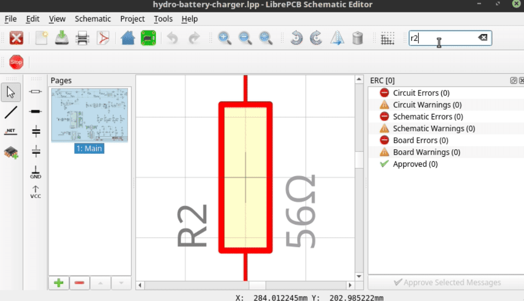
One of the more well-known tools from the “new generation” of free PCB design software is LibrePCB. The majority of older tools date back to a time when component choices were constrained and computer power was lower. If those tools were completely redone, they might resemble LibrePCB, which caters to a variety of user experiences. At the same time, everyone is eager to benefit from a broad and quickly expanding spectrum of electronic parts, modules, and sensors.
The software already has a solid reputation for being simple to use and having an intuitive interface. While it currently lacks features like 3D visualization, its functionality is expanding quickly.
03. Fusion Electronics
The PCB and circuit design tool from Autodesk, Fusion Electronics (also known as Fusion 360 Electronics), is directly integrated into their Fusion 360 CAD program.
A license cost is required for professional use, but Fusion 360 subscribers have access to a limited version for personal use. Similar to EAGLE, there is a limit of two schematic sheets, two board layers, and an 80 cm2 maximum board area, but this should be sufficient for the majority of hobbyist uses.
02. Proteus
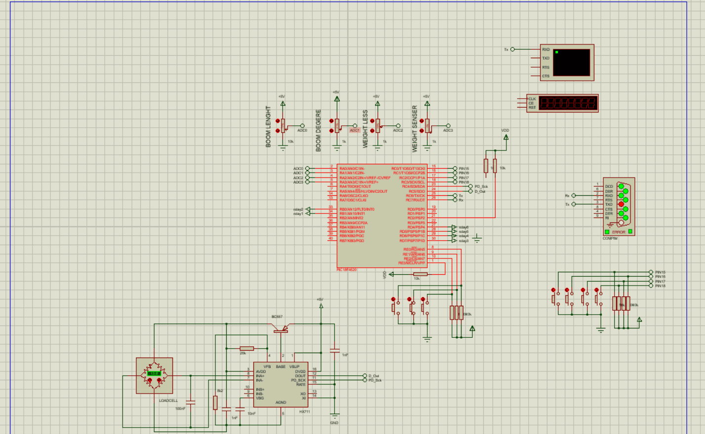
Labcenter Electronics Ltd., a business established by John Jameson in the United Kingdom in 1988, created the Proteus electronic CAD system. Proteus is widely used and sold in more than 50 countries.
Specifications and features
There are two primary software programs in this suite:
- Proteus ISI: simulation of electricity and diagram creation
- Proteus ARES: a tool for autonomous component positioning in printed circuit wiring
01. Cadence OrCAD PCB Designer
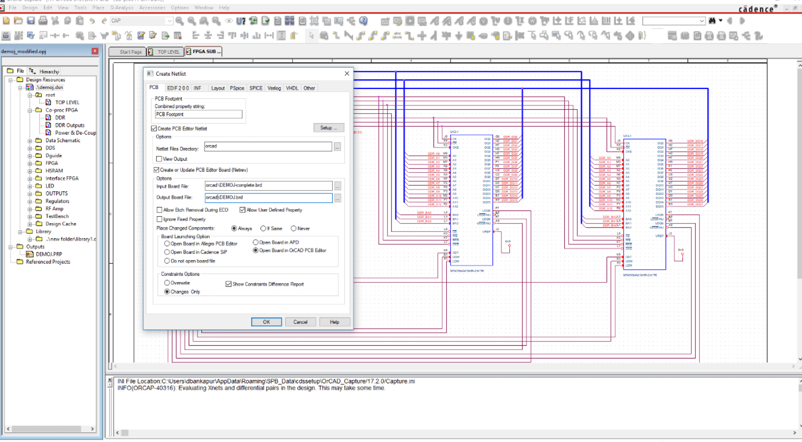
Cadence Design Systems, a world leader in electronics CAD software, was established in 1988 as a result of the merging of SDA Systems and ECAD. It is a NASDAQ-listed business with headquarters in San José, California, and an annual revenue of roughly $2 billion.
OrCAD and Allegro PCB Designer are both published by Cadence.
Specifications and features
- Routing, arrangement, and diagrams
- Real-time routing that is interactive and has built-in restrictions
- Automatic development and updating of shapes
- Automatic BGA support
This was about “Top 20 Tools To Design A Schematic“. I hope this article may help you all a lot. Thank you for reading.
Also, read:
- 10 Free ADAS Projects With Source Code And Documentation – Learn & Build Today
- 100 + Electrical Engineering Projects For Students, Engineers
- 100+ Indian Startups & What They Are Building
- 1000+ Automotive Interview Questions With Answers
- 1000+ Electronics Projects For Engineers, Diploma, MTech Students
- 1000+ MATLAB Simulink Projects For MTech, Engineering Students
- 2000+ Embedded Systems Interview Question Bank
- 2026 Hackathons That Can Change Your Tech Career Forever