
Hello guys, welcome back to my blog. In this article, I will discuss the top electric drives projects for MTech and engineering students, projects on DC machines, projects on Brushless DC with Trapezoidal Back Emf, projects on Brushless AC with Sinusoidal Back Emf, projects on Induction Motor, etc.
If you have any doubts related to electrical, electronics, and computer science, then ask question. You can also catch me @ Instagram – Chetan Shidling.
Also, read:
- Electric Vehicle Charging station, Working, Types Of Charging Stations
- Top 15 Transmission And Distribution Companies In The World
- Types Of Cell Balancing Topologies, Active And Passive Cell Balancing
Electric Drives Projects
Project On DC Machine
01. Position Control with Non-Ideal Transducer
The motor position is measured with an encoder, which returns a quantized signal that ranges between 0 and 2π. (For the quantized quantities Simulink has a dedicated block called Quantizer). The measured velocity can be obtained by deriving the position signal with a transfer function such as,
Where T is a multiple of the sampling period (at least T = Tc). Then, you will be asked to:
- Realize a position control loop able to properly track small (i.e. θref = 1×360◦) and big (i.e. θref = 100×360◦) step input signals.
- Compare the behavior of the real system with the ideal one, for different values of T.
N.B. The encoder returns a value in the range [0, 2π], while the reference position can be a number greater than 2π (the mechanical shaft can do more than 1 rotation to reach the reference). As a consequence, it should be found a way that allows the control system to represent rotations of the shaft not only included in the range [0, 2π].
02. Position Control with Elastic Load
Starting from the position control explained during classroom hours, modify the control the scheme in order to make it able to achieve the following tasks:
- Compensate the back emf in the current control loop.
- Modify the anti-windup of the PI regulator in order to compensate for the back emf effect.
- The position control loop must be able to properly track small (i.e. θref = 1×360◦) and big (i.e. θref = 100×360◦) step input signals. For that task, let us consider an ideal transducer of velocity. For what concerns the position, it can be found by integrating the measured velocity.
- Let us suppose that the mechanical shaft which connects the motor and the load to each other is quite long and, for that reason, it cannot be considered rigid anymore. The mechanical equations become as follow:
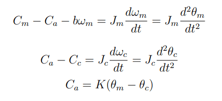
Where K is the elastic constant of the shaft and it can be assumed equal to 20 Nm/rad, Ca is the useful torque, ωc, and ωm are the load and motor velocity, respectively. The resistant torque is proportional to the velocity and it keeps the expression in the case of rigid coupling.
- Compare the drive’s behavior in cases of rigid and elastic coupling. Explain the speed and position profiles of both motor and load.
- Let us suppose that the resistant torque is null, determine the transfer functions between motor velocity and motor current, load velocity, and motor velocity.
- Relying on the previous point, tune the current, velocity, and position control loop so that they do not experience significant oscillations.
03. Field Weakening Operation Control
In this project, you have to design a control scheme able to achieve the following tasks:
- Modify the anti-windup of the PI regulator in order to compensate for the back emf effect.
- Implement the field weakening operation control. For that task, the torque constant can be written as,
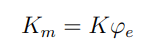
where K = 1. The nominal excitation current is 5 A. For the sake of simplicity, it can be assumed that,
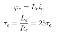
The control system has, in addition to the ordinary control loops, also the current excitation loop. The current reference has to be kept constant and equal to 5 A up to the nominal velocity, then it has to decrease with hyperbolic law. The flux has to be automatically generated based on the voltage request given by the regulator associated with the armature current.
Project On Brushless DC with Trapezoidal Back Emf
04. Velocity Control
Realize an electric drive (including the motor plus the control of torque and velocity) for a DC brushless motor with a trapezoidal back emf. Here is some advice useful for the model implementation on Simulink:
- The model implements the current equations ia, ib, while ic = −ia − ib.
- The back emf of each phase can be found as the product between the pulsation and the phase excitation flux, which depends on the position (use look-up table on Simulink).
- In order to avoid the division by 0 at the beginning of the simulation, the torque can be calculated as the sum of current multiplied by flux (avoid the expression torque=mechanical power*velocity).
- For the calculation of the reference currents, use hysteresis regulators instead of PI regulators.
Project On Brushless AC with Sinusoidal Back Emf
05. Position Control with Non-Ideal Transducer
With reference to the same encoder given for the project 02 Position Control with Elastic Load:
- Realize a position control loop and study its behavior when the discretization step is 2π/1024, 2π/256, and 2π/64.
- Modify the anti-windup of the PI regulator in order to make it able to properly track the Input Voltage (This is not a trivial task, since the voltage constraint is V^2 d + V^2 q < V^2 max).
06. Modelling a Cogging Torque Disturbance Compensator
By considering a Permanent Magnets Machine with sinusoidal back emf, model the electric drive so that it will be able to:
- Compensate sinusoidal torque disturbances depending on a multiple of the rotor angle (and unknown phase angle α) that has the following expression
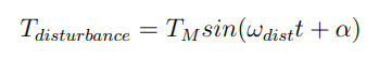
N.B. The speed control system is required to achieve that task.
07. Field Weakening Operation Control
By implementing the motor equations on a rotating d,q reference frame realize a Field Weakening Control System. The tasks to be carried out are:
- Figure out the maximum negative value achievable by the d axis current.
- Show what is the velocity limit of the motor and explain the reasons.
- Plot and describe the characteristics of both Mechanical Power and Mechanical Torque in normal operating conditions and in field weakening operating conditions.
Project On Induction Motor
08. Scalar Control (V/f = Const)
By considering an Induction Motor, realize a Closed Loop Control System able to:
- Control the Velocity.
- Control the Slip.
N.B. When modeling the motor, choose real parameter values from a datasheet.
09. Vector Control (Rotating d, q Reference Frame)
The project aims to model and tune a Torque Control Loop and a Velocity Control Loop by implementing the motor equations on a rotating d, q reference frame. In particular, the requirements you are asked to fulfill are:
- Realize the models of the induction motor and the mechanical load. (As in the previous project, use real values from a datasheet).
- Realize the Control System (including the inverter) and make it able to properly track a reference profile of Torque and Velocity.
Appendices
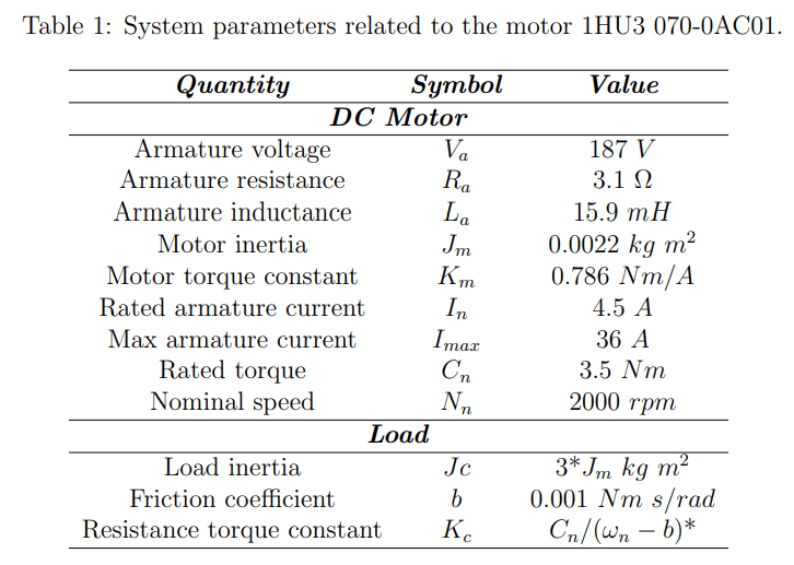
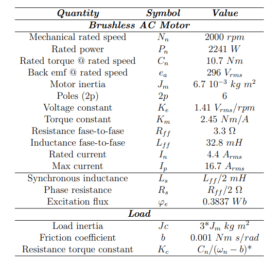
*HP: Steady-state conditions and operating speed equal to nominal speed.
10. DC Motor
11. Brushless AC with Sinusoidal Back Emf
This was about ” Electric Drives Projects “. I hope this article ” Electric Drives Projects ” may help you all a lot. Thank you for reading.
Also, read:
- 10 Free ADAS Projects With Source Code And Documentation – Learn & Build Today
- 10 Tips To Maintain Battery For Long Life, Battery Maintainance
- 10 Tips To Save Electricity Bills, Save Money By Saving Electricity
- 100 (AI) Artificial Intelligence Applications In The Automotive Industry
- 100 + Electrical Engineering Projects For Students, Engineers
- 100+ Indian Startups & What They Are Building
- 1000+ Automotive Interview Questions With Answers
- 1000+ Electronics Projects For Engineers, Diploma, MTech Students