Hello guys, welcome back to my blog. In this article, I will discuss what is a bidirectional dc-dc converter, the circuit diagram of a bidirectional dc-dc converter, the working of a bi-directional dc-dc converter, etc.
Subscribe our website for more updates. You can also catch me @ Instagram – Chetan Shidling.
Also, read:
- Difference Between C Language And Embedded C.
- UART Working, Diagram, Applications, Advantages, Disadvantages.
- What is TCP Or IP Protocol, Working, Diagram, Layers, With Example.
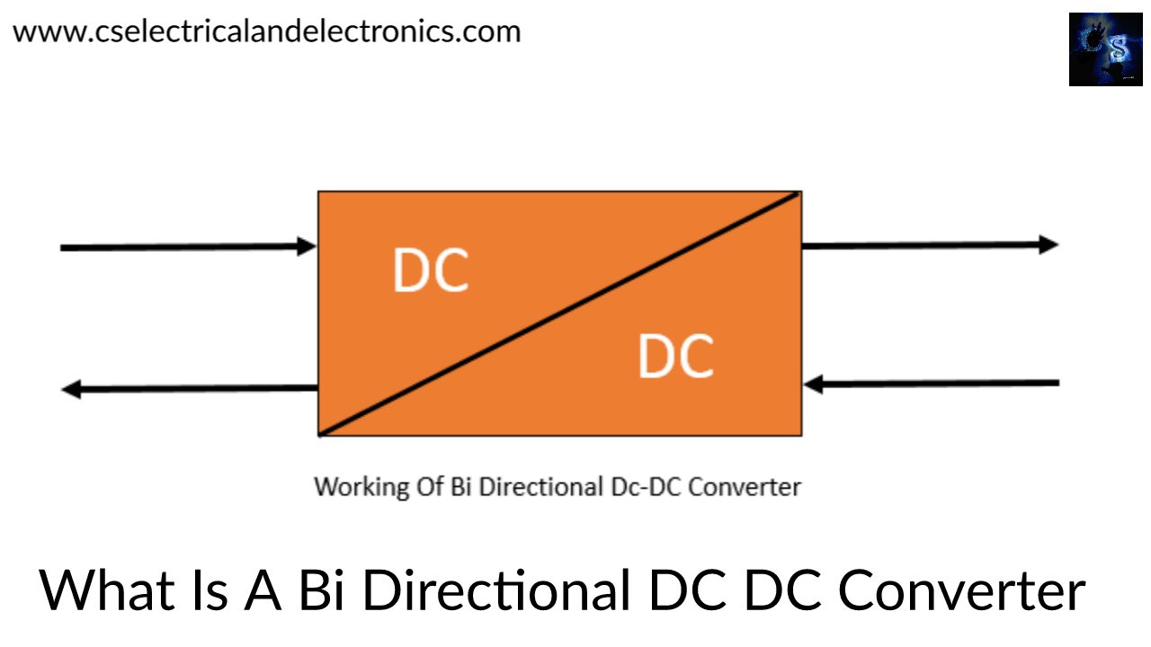
Bidirectional DC-DC Converter
This type of converter nowadays is mainly used in electric vehicles. It is also called a Half-Bridge DC-DC converter. When the Buck and the boost converters are connected in antiparallel across each other with the resulting circuit is primarily having the same structure as the basic Boost and Buck structure but with the combined feature of bidirectional power flow is called Bi directional dc-dc converter. It works in both directions.

The above circuit can work in buck or boost mode depending on the switching of the Mosfets Q1 and Q2. The switches Q1 or Q2 in sequence with the anti-parallel diodes D1 or D2 (acting as a freewheeling diode) respectively, which makes the circuit step up or step down the voltage connected across them. The bidirectional operation of the above circuit can be described in the below two modes as follows:
Mode 1 (Boost Mode): In this mode switch Q2 and diode D1 begin into conduction depending on the duty cycle whereas the switch Q1 and diode D2 are off all the time. This mode can moreover be divided into two intervals depending on the conduction on the switch Q1 and diode D2.
Interval 1 (Q2-on, D2-off; Q1-off, D2-Off): In this mode Q2 is on and hence can be examined to be short-circuited, hence the lower voltage battery charges the inductor and the inductor current goes on rising till not the gate pulse is separated from the Q2. Also since the diode D1 is reversed biased in this mode and the switch Q1 is off, no current flows into the switch Q1.
Interval 2 (Q1-off, D1-off; Q2-off, D2-on): In this mode, Q2 and Q1 both are off and therefore can be considered to be opened circuited. Now since the current flowing into the inductor cannot change immediately, the polarity of the voltage across it reverses and hence it starts acting in series with the input voltage. Therefore the diode D1 is forward biased and so the inductor current charges the output capacitor C2 to a greater voltage. Therefore the output voltage boosts up.
Mode 2 (Buck Mode): In this mode switch Q1 and diode D2 begin into conduction depending on the duty cycle whereas the switch Q2 and diode D1 are off all the time. This mode can moreover be divided into two intervals depending on the conduction on the switch Q2 and diode D1.
Interval 1 (Q2-on, D2-off; Q1-off, D2-Off): In this mode, Q1 is on and Q2 is off. The greater voltage battery will charge the inductor and the o/p capacitor will get charged by battery.
Interval 2 (Q1-off, D1-off; Q2-off, D2-on): In this mode, Q2 and Q1 both are off. Again as the inductor current cannot change instantaneously, it gets discharged via the freewheeling diode D2. The voltage across the load is stepped down as correlated to the input voltage.
A comparison between the features of the non-isolated bidirectional topologies have been explained below:
01. During step-up mode, in the buck-boost bidirectional converter the RMS value of the current in the inductor and the power switches is greater by an amount equivalent to the output current as compared to the buck-boost cascade bidirectional converter. Furthermore, the capacitor RMS current also excels in the former case by an amount of the 1/3rd of the output current. Hence in the bidirectional buck-boost converter the power switches, inductor, and the capacitor work under more thermal and electrical stresses as compared to the buck-boost cascade converter following in greater power loss and also creating the saturation of the inductor core. Also as the stress on the MOSFET and the diode is higher, the buck-boost bidirectional converter needs power devices with larger device ratings. Higher RMS currents also result in greater conduction losses and thus reducing the overall efficiency of the buck-boost bidirectional converter.
02. However the no of devices needed by the cascade buck-boost converter is double the number of devices in the buck-boost bidirectional converter. This problem can be resolved by using the Half-Bridge Bidirectional DC-DC Converter. It has the same no devices as the buck-boost bidirectional converter and can be used instead of the buck-boost cascade bidirectional converter for the applications that need the boost operation only in 1 direction and the buck in the other direction.
03. The main benefits of the half-bridge bi-directional converter as correlated to the bi-directional Cuk converter is that it only needs one inductor instead of two and that too half the value of the latter, as well as the power switches ratings needed for the half-bridge bidirectional converter, is very lower as compared to the Cuk converter. Also, the efficiency of the half-bridge converter is higher than the Cuk converter because of the lower inductor current and hence lower conduction as well as lower switching losses.
I hope this article “Bidirectional dc dc converter” may help you all a lot. Thank you for reading.
Also, read:
- 10 Free ADAS Projects With Source Code And Documentation – Learn & Build Today
- 10 Tips To Maintain Battery For Long Life, Battery Maintainance
- 10 Tips To Save Electricity Bills, Save Money By Saving Electricity
- 100 (AI) Artificial Intelligence Applications In The Automotive Industry
- 100 + Electrical Engineering Projects For Students, Engineers
- 100+ Indian Startups & What They Are Building
- 1000+ Automotive Interview Questions With Answers
- 1000+ Electronics Projects For Engineers, Diploma, MTech Students
- 1000+ MATLAB Simulink Projects For MTech, Engineering Students
- 2000+ Embedded Systems Interview Question Bank