Hello guys, welcome back to my blog. In this article, I will discuss what is a dc motor, the working of dc motor, the operation of dc motor, the types of dc motor, the equations of dc motor, etc.
If you have any doubts related to electrical, electronics, and computer science, then ask questions. You can also catch me on Instagram – CS Electrical & Electronics And Chetan Shidling.
Also, read:
- What Is Reactor, Types Of Reactors Used In Power Systems, Applications
- Electric Vehicle Charging station, Working, Types Of Charging Stations
- Top 15 Transmission And Distribution Companies In The World
What Is A DC Motor
DC Motor
- A motor converts electrical energy into mechanical energy.
- The electrical energy is supplied as input by a D.C supply.
Operation Of DC Motor
The principle of the operation of a DC motor is “when we place the current-carrying conductor in a magnetic field, it experiences a mechanical force”. The field winding produces a required magnetic field, while the armature conductors play a major role in current-carrying conductors. The conductors will be placed on the slots.
The individual force experienced by the conductors acts as twisting or turning forces which are termed as torque. Let’s consider a single conductor placed in a magnetic field which will be produced by a permanent magnet, while in a DC motor it will be produced by field winding. The separate voltage Supply is given to this conductor, which carries a current in a particular direction. Let’s imagine it carries current away from the observer.
This conductor produces its own magnetic flux around it. The direction of this flux will be determined by the right-hand thumb rule. The direction of the flux and current is considered along clockwise. So now totally we will be having two fluxes.
- Flux produced by a permanent magnet which will be termed as main flux.
- The flux produced by the current-carrying conductor.
And both fluxes are in the same direction.
There will be a gathering of the flux lines, as two fluxes will help one and each other on the left side of the conductor. As against this, the two fluxes are in the opposite direction on the right side of the conductor. Hence they tried to cancel each other. Because of this, the density of the flux line in this area will get weakened. On the left side of the conductor, the flux density area will be moved and on the right side of the conductor, the flux density area will be less. The flux acts like rubber around the conductor and this induces a mechanical force on the conductor which acts from higher flux density area to lower flux density area.
Voltage Equation For DC Motor
V = Eb + IaRa + brush drop
Eb= Back e.m.f
IaRa= Armature voltage drop
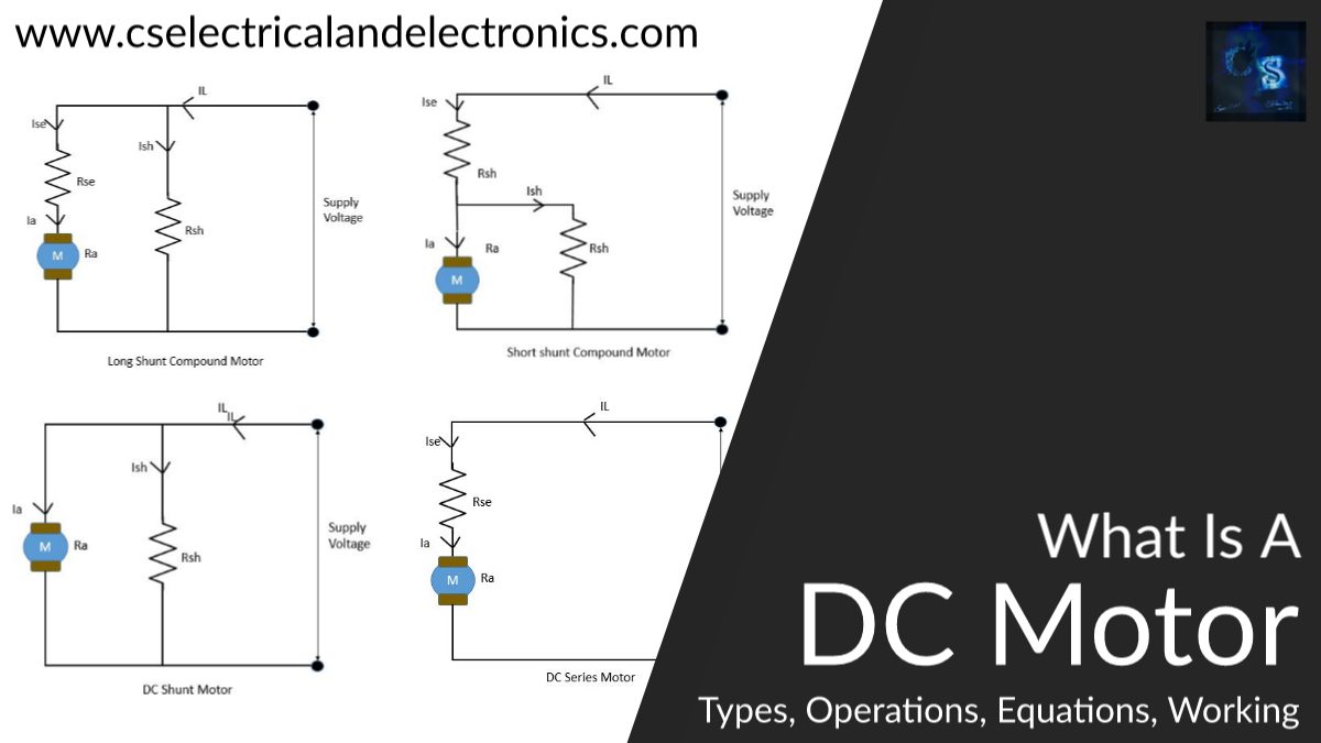
Types Of DC Motor
- DC series motor.
- DC shunt motor.
- DC compound motor – It is again classified as;
- Long shunt motor.
- Short shunt motor.
- Cumulative compound motor.
- Differential compound motor.
DC Series Motor
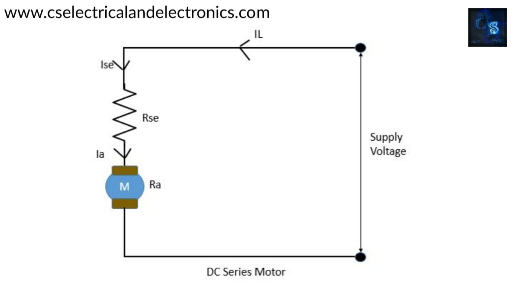
- In this type of motor, the field winding will be connected in series with armature winding and the supply.
- Rse= resistance of the series field winding and Which is having a smaller value and having a large cross-sectional area and having a fewer number of turns.
Voltage equation of series motor
V = Eb+Ia (Ra+Rse) + Vbrush
Operation Of dc series motor
An external source will be applied across this series configuration. One end of the voltage source will be connected across field winding, while the other end will be connected across the armature winding through the brushes. Initially, when we supply, the motor draws a large amount of current because both the windings are made with conductors that offer minimum resistance to the flowing current.
The large current along the windings produces a strong magnetic field. This field produces high torque to the armature shaft resulting in the rotation of the motor at its maximum speed. If the series model started once, it offers high speed and torque, but slowly with increasing speed, its torque will be decreased because of its reduced current. This further helps in increasing the heat dissipation of the motor.
The amount of torque generated by the motor will be directly proportional to the winding current. The higher current demands a higher supply.
DC Shunt Motor
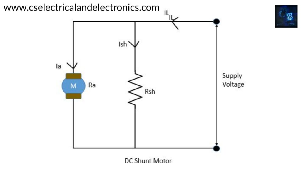
- The field winding will be connected in parallel with the armature winding and this parallel the combination will be connected across the supply.
- Rsh = shunt resistance. Ra = Armature resistance. (Rsh > Ra)
- The field winding will be having a less cross-sectional area with a large number of turns.
Voltage equation for dc motor
V= Eb+ IaRa
Eb= Back e.m.f
IaRa = Armature voltage drop.
Operation of dc shunt motor
When we supply voltage to the DC shunt motor, it draws a very low current due to more resistance of the shunt winding. The shunt field winding will be having more turns and this helps to generate a strong magnetic field. Armature winding will draw more current and generate a high magnetic field. When the magnetic field interacts with shunt winding then the motor starts to rotate. The rotational torque will be produced and increase when the magnetic field grows stronger.
This results in an increase in the speed of the motor. It has a feedback mechanism that controls its speed. The armature rotates in a magnetic field that produces electricity. This e.m.f will be generated in the opposite direction So the current through armature winding will be decreased and the speed of the motor is self-regulated.
The shunt winding doesn’t tolerate high current at starting because of its fine wire build. That’s why a shunt motor will be used to handle small shaft loads that need low torque initially.
DC Compound Motor
In this type of motor, some parts of the field winding will be connected in series with the armature winding and another part of the field winding will be connected in parallel with the armature winding. We have mainly four types in DC compound motor.
01. Long shunt compound motor

In this type, long shunt winding(it should be Rls, in the image it is Rsh) is in parallel with both series shunt and armature.
Voltage equation of long shunt compound motor
V = Eb + Ia ( Ra + Rse ) + Vbrush
02. Short shunt compound motor
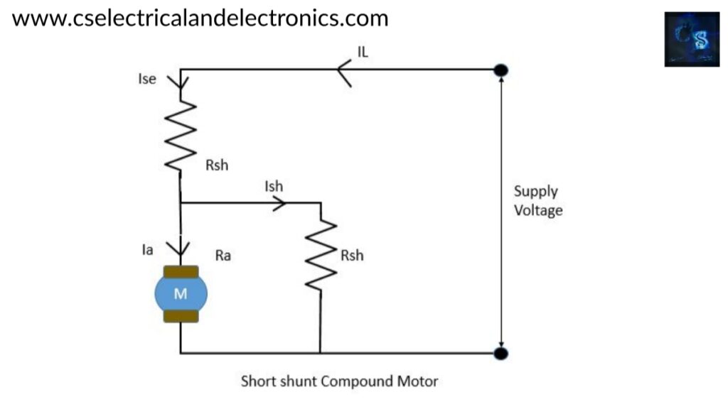
In this type, short shunt winding will be connected in parallel with the armature only.
Voltage equation of short shunt compound motor
V = Eb + Ise Rse + IaRa + Vbrush
03. Cumulative compound Motors
In this, the two field windings will be wounded in such a way that the flux produced by these two field windings will always help each other.
04. Differential compound Motors
In this, the fluxes produced by two field windings will be opposite to each other.
I hope this article may help you all a lot. Thank you for reading.
Also, read:
- 10 Tips To Maintain Battery For Long Life, Battery Maintainance
- 10 Tips To Save Electricity Bills, Save Money By Saving Electricity
- 100 (AI) Artificial Intelligence Applications In The Automotive Industry
- 100 + Electrical Engineering Projects For Students, Engineers
- 100+ Indian Startups & What They Are Building
- 1000+ Automotive Interview Questions With Answers
- 1000+ MATLAB Simulink Projects For MTech, Engineering Students
- 2024 Is About To End, Let’s Recall Electric Vehicles Launched In 2024