Hello guys, welcome back to my blog. In this article, I will discuss what is cycloconverter, the working of cycloconverter with circuit diagram, types, benefits, drawbacks, applications of cycloconverter, etc.
If you have any doubts related to electrical, electronics, and computer science, then ask question. You can also catch me @ Instagram – Chetan Shidling.
Also, read:
- What is Linear Integrated Circuits, Why It is Used, Working & Applications
- What Is RAM And ROM, Their Types, Advantages, Disadvantages
- Embedded System Questions Asked In Online Test At LTTS, Robert Bosch
What Is Cycloconverter
There are two forms of electrical energy is used in the Industries known as DC (Direct current) and AC (Alternating Current). The constant current and voltage are available as per the requirement, but there are few machines that consist of different voltage ratings, current ratings, and frequency, etc. To overcome this type of problem different electronic devices which are made up of thyristors or transistors are used such as voltage controller, Inverter and Cyclo converter and many more. Every electronic device has its own different function according to the configuration of the circuit.
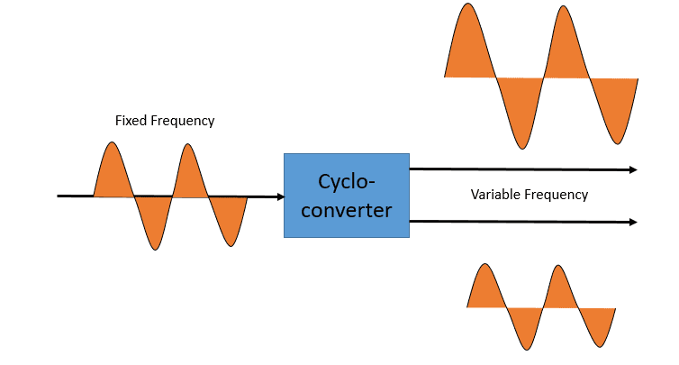
A device that converts input power at one frequency to output power at a different frequency with one stage conversion is called a “Cyclo converter”. Cyclo converter converts the constant frequency AC wave to the variable frequency AC wave without changing the constant parameters. Simply it can be called the frequency converter.
According to the output frequency, there are two types of cyclo converters, namely
01. Step-up Cycloconverter:
In this type of converter, the output frequency is greater than the input frequency. The line commutation is used for obtaining the greater output frequency.
02. Step-down Cycloconverter:
In this type of converter, the output frequency is less than the input frequency. The forced commutation is used for obtaining the lower output frequency.
Coming to the operating modes cyclo converters are classified into two types such as
01. Blocking Mode Cycloconverter
Cyclo converter consists of two divisions as the positive converter and the negative converter. The divisions will conduct according to the supply voltage. The positive converter will give the desired output voltage when there is a positive load current, during this operation the negative converter is in blocking condition. The Negative converter will give the desired output voltage when there is a negative load current, during this operation the positive converter is in blocking condition.
This type of cyclo converters operation is known as blocking mode operation and the cyclo converters which perform this type of operation are known as the blocking mode cyclo converters. These are of high efficiency and low cost and minimized size. These converters are mainly used in industries as only one converter is working at a time and there will be no need for inter-group reactors.
02. Circulating Mode Cycloconverter
Circulating mode is completely opposite to the blocking mode as the converter conducts in both states of operations. The cyclo converter works in the positive converter and negative converter at a time. Due to these types of operations, there will be a problem with short circuits. To prevent the short circuit the Intergroup reactors are used.
These Intergroup reactors are connected between the converters to avoid the short circuit. The circulating current is a unidirectional path in the circulating mode. The cyclo converters that operate in the circulating mode are called the circulating mode cyclo converters.
According to the applications, there are mainly four types of cyclo converters used. The working of the cyclo converters is different for every respective type.
- Single phase cyclo converter
- Center-tapped cyclo converter
- Three phase to single phase cyclo converter
- Three phase to Three Phase cyclo converter
The Single-phase to three-phase cyclo converters are not yet manufactured but there are some practicals conducted to drive the induction motor using that but the output frequency is half of the input hence the practical usage of this type of cyclo converter is not possible.
Working Of Cyclcoconverter
Single-Phase Cycloconverter:
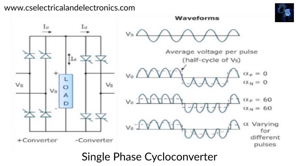
The above figure shows the principle of operation of a single-phase cyclo converter. It mainly consists of two groups of rectifiers one forming a positive group and the other forming the negative group which is feeding a common load. The input to both groups is the same. The waveforms of input voltage consist of alternately positive and negative half-waves of frequency.
The firing pulse is zero, the positive group allows all positive half-waves to pass through and also converts the negative half-waves into positive half-waves. The negative group allows all negative half-waves to come to it and also converts positive half-waves into the negative ones according to the firing angle value. This is how the single frequency cyclo converter works.
Centre Tapped Cycloconverter:
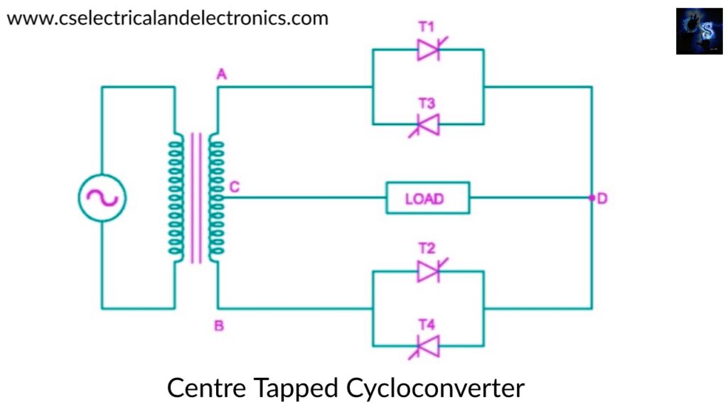
The centre tapped cyclo converter is shown in the above figure connected to the transformer. The secondary winding of the transformer is provided with the centre tappings. It consists of four thyristors, two of these thyristors T1 and T3 are formed as the positive group and the other two T2 and T4 are formed as the negative group.
The load is connected in the midpoint of the secondary winding. During the positive half cycle, T1 and T4 are switched on and conducted and during the negative half cycle, T2 and T3 are switched. At different firing angled the commutation and the conduction will be operated.
Three-Phase To Single-Phase Cycloconverter:
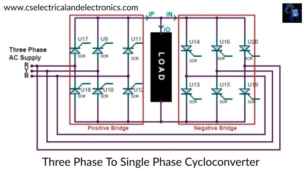
A three-phase to single-phase cyclo converter is used to convert the three-phase frequency into the single-phase frequency. These types of converters operate in four quadrants such as +V, +I, -V, -I in two modes as inverting and rectifying. These converters operate in the blocking mode operation. The +V and +I are in the rectifying mode and the –V and –I are in the inverting mode.
The positive converters will produce the positive current and the negative converters will produce the negative current which is given to load respectively. Only one converter will be operated at a time hence these are also called blocking mode cyclo converters.
Three-Phase To Three-Phase Cycloconverter:
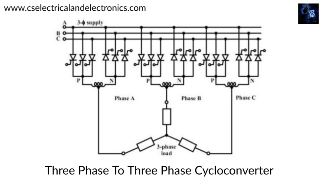
The three-phase cyclo converter converts the three-phase fixed ac frequency into variable ac frequency. The three-phase cyclo converter is formed by the combination of 3 three-phase to single-phase converters. The working is also similar to the three-phase to single-phase converter but the circuit design will be different as the wye and delta connections are involved according to the requirement.
The output waveform will be 120 degrees shifted as the conduction process in the three-phase cyclo converter involves the phase shift conduction. This is the main principle behind the working of a three-phase to three-phase cyclo converter.
These are the different types of cyclo converters and their working according to the requirement.
Advantages Of Cycloconverter
01. The cyclo converter operates on the line commutation, so additional equipment is not required.
02. Due to the single-stage operation technique, the efficiency of the cyclo converter is very high.
03. The power transfer is possible at any power factor value.
04. The cyclo converter generates the sinusoidal waveform for low output frequency also.
05. Failure of the one thyristor will not affect the output of the converter.
Disadvantages Of Cycloconverter
01. Due to the usage of a large number of thyristors the control circuitry becomes complex.
02. Power factor is too low at the large values of firing angle.
03. The distortion is very high at the lower frequencies.
04. Smooth control for step-less output frequency is not possible.
Applications Of Cycloconverter
01. Low speed, high power AC motor drives
02. HVDC transmission systems
03. Static VAR generation
04. Induction heating systems
05. Cement mill drives
06. Grinding mills and rolling mills
07. Mine winders as well as mine hoists
08. Electric traction
09. Conversion of variable–speed alternator voltage into constant frequency voltage in air crafts and ship boards.
This was about “What Is Cycloconverter”. I hope this article may help you all a lot. Thank you for reading.
Also, read:
- 10 Free ADAS Projects With Source Code And Documentation – Learn & Build Today
- 100 + Electrical Engineering Projects For Students, Engineers
- 100+ Indian Startups & What They Are Building
- 1000+ Automotive Interview Questions With Answers
- 1000+ Electronics Projects For Engineers, Diploma, MTech Students
- 1000+ MATLAB Simulink Projects For MTech, Engineering Students
- 2000+ Embedded Systems Interview Question Bank
- 2026 Hackathons That Can Change Your Tech Career Forever