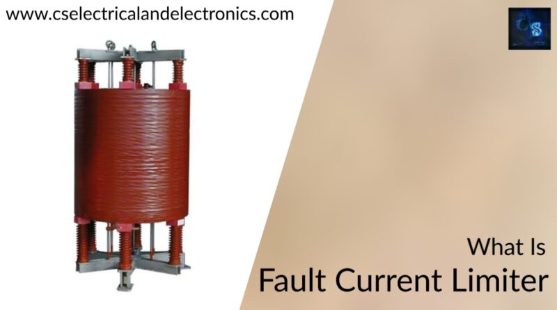
What Is Fault Current Limiters In Power System, Advantages, Applications
Hello guys, welcome back to my blog. This article will be on what is fault current limiters in power systems, the types of current limiters, applications, and the advantages of fault current limiters.
If you have any electrical, electronics, and computer science doubts, then ask questions. You can also catch me on Instagram – CS Electrical & Electronics And Chetan Shidling.
Also, read:
- What Is SoC, SoH, SoP, SoT, SoS In Battery, State Of Charge, Health
- Fuel Cells Can Be Used As Backup Power Supply In Future
- Top 100+ MATLAB Simulink Projects With SLX File For Engineers
What Is Fault Current Limiters In Power System
Fault current limiters (FCLs) are unique power system devices that reduce large short-circuit currents to considerably more manageable levels for existing safety equipment such as circuit breakers (CBS). FCLs are often placed to lower the available fault current to a level that the CB can safely interrupt before it begins its opening operation. The fault current is limited by the FCL to a fixed level based on the system setup and circumstances.
Engineers used to be forced to either upgrade existing equipment to protect the state from increased short-circuit capacity (if replacements can safely interrupt the new short-circuit level) or find a way to lower the short-circuit rating, such as bus splitting, increasing transformer impedance, and so on, to protect the system from the increased short-circuit capacity. The FCL enables the engineer to use the chosen technology without having to change the entire system of protective equipment, such as circuit breakers, which may be rather costly.
Fault Current Limiters (FCLs) operate as an extra high impedance to keep excessive fault currents under control. FCLs have nearly little impedance and are ‘invisible’ to the system in normal operation. FCLs, unlike fuses or disconnectors, do not disconnect in the event of a malfunction. They can resume regular functioning once the fault current has passed. FCLs can respond quickly and reduce the short circuit current, allowing the CB to operate within its nominal performance range if necessary. FCLs are often employed at low and medium voltage levels.
Technology Types & Classsification
FCL is divided into two categories, each of which can be further divided into subcategories based on technology.
Non-superconducting FCL:
- Saturable core FCLs take advantage of the nonlinear properties of ferromagnetic materials to achieve a high inductance.
- Solid-state FCLs employ a high-power semiconductor device to implement an FCL and can be classed as serial, bridge, or resonance.
Superconducting FCL (SFC):
- The capacity of the superconductor to shift state from superconducting to resistive, known as the superconductor quench,’ is used in resistive SFCLs.
- SFCLs that are inductive work like a transformer and have a short superconducting secondary winding. The superconductor quench is the resistance of the secondary winding.
- If a fault develops, the bridge type of SFCLs employs power thyristors and power diodes to stop fault currents.
Superconducting fault current limiter
The highly quick loss of superconductivity (known as “quenching”) over a crucial combination of temperature, current density, and the magnetic field is exploited by superconducting fault current limiters. Current passes through the superconductor with minimal resistance and very low impedance in typical operation.
When a defect occurs, the superconductor quenches, its resistance skyrockets, and the currents are routed to a parallel circuit with the required higher impedance.
(Because the normally-conducting superconductive material does not have a high enough resistance, the structure cannot be used as a circuit breaker.) It is just high enough to heat the material sufficiently to melt it.)
Resistive or inductive fault current limiters are the two main types of superconducting fault current limiters.
The current in a resistive FCL flows straight through the superconductor. The sudden spike in resistance when it quenches decreases the fault current from what it would otherwise be (the prospective fault current). A DC or AC resistive FCL can be used. If it’s AC, there’ll be a continuous power dissipation from AC losses (superconducting hysteresis losses), which the cryogenic system will have to compensate for. An AC FCL is normally manufactured of non-inductively wrapped wire; otherwise, the device’s inductance would cause a continual power loss in the system.
Advantages & field of application
System operators or commercial clients can optimize the system by using standard solutions with defined (low) nominal short circuit currents by adding FCLs. The following are some of the major benefits:
- The system short-circuits current is reduced, allowing the CBs to operate within their normal performance range.
- Because of the decreased overall source impedance, voltage sags and flickers are reduced.
- Harmonics are reduced due to the decreased overall source impedance.
Circuit breakers are used in electric power distribution systems to disconnect electricity in the event of a breakdown, but they want to disconnect the smallest feasible area of the network to optimize dependability. This implies that even the tiniest circuit breakers, as well as all associated wires, must be capable of disconnecting high fault currents.
When the electrical supply is enhanced, such as by adding extra generation capacity or cross-connections, a problem occurs. Because they enhance the amount of power that may be delivered, all branch circuit bus bars and circuit breakers must be changed to accommodate the new higher fault current limit.
When dispersed energy, such as wind farms and rooftop solar power, is added to an existing electric grid, this offers a specific difficulty. It’s ideal to be able to add more power sources without requiring major system modifications.
Adding electrical resistance to the circuit is a straightforward solution. This slows the rate of current increase, limiting the amount of fault current that may build up before the breaker is tripped. However, this restricts the circuit’s capacity to meet quickly changing demand, resulting in unstable power when heavy loads are added or removed.
To summarise, A fault current limiter is a nonlinear device with a low impedance at normal current levels but a greater impedance when fault current levels are present. Furthermore, before a circuit breaker may trip a few milliseconds later, this transition occurs at a breakneck speed. (To reduce arcing, high-power circuit breakers are synced to the alternating current zero-crossing.) The electricity is not entirely disconnected during the fault because it is unreliable. The fault current limiter returns to normal functioning when the faulting branch is unplugged.
This was about “What Is Fault Current Limiters In Power System“. I hope this article may help you all a lot. Thank you for reading.
Also, read:
- 10 Tips To Maintain Battery For Long Life, Battery Maintainance
- 10 Tips To Save Electricity Bills, Save Money By Saving Electricity
- 100 (AI) Artificial Intelligence Applications In The Automotive Industry
- 100 + Electrical Engineering Projects For Students, Engineers
- 1000+ Control System Quiz, Top MCQ On Control System
- 1000+ Electrical Machines Quiz, Top MCQs On Electrical Machines
- 1000+ MATLAB Simulink Projects For MTech, Engineering Students
- 50 Tips To Save Electricity At Home, Shop, Industry, Office
Author Profile
- Chetu
- Interest's ~ Engineering | Entrepreneurship | Politics | History | Travelling | Content Writing | Technology | Cooking
Latest entries
 All PostsApril 29, 2024Top 11 Free Courses On Battery For Engineers With Documents
 All PostsApril 19, 2024What Is Vector CANoe Tool, Why It Is Used In The Automotive Industry
 All PostsApril 13, 2024What Is TCM, Transmission Control Module, Working, Purpose,
 All PostsApril 12, 2024Top 100 HiL hardware in loop Interview Questions With Answers For Engineers


