Hello guys, welcome back to our blog. In this article, we will discuss what is LT line, the construction of LT lines, the code of practice related to distribution lines, what is low tension lines, and the construction of low tension lines.
If you have any electrical, electronics, and computer science doubts, then ask questions. You can also catch me on Instagram – CS Electrical & Electronics.
Also, read:
- Top 20 Innovations In The Automotive Industry, Automotive Technologies
- Top 10 Electrical Wire Manufacturing Companies In The World
- Top Electric Vehicle Interview Questions With Answers Must Know
What Is LT Line Or Low Tension Line
Code of Practice for Distribution lines
Let’s discuss the points.
The following points are:
1. While preparing a route map or topo sheet following should keep in mind:
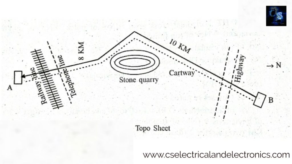
TOPO Sheet is the sheet showing the plan of the area where the line is proposed to be drawn. Such a sheet is prepared after conducting the surveys. The topo sheet represents the route of the proposed line indicating the length, deviations, highway crossing, railway crossing, telephone line crossing, etc.
If the topo sheet represents forest area, in the estimate we have to provide labor charges for cleaning the forest. The top sheet may also represent the river, water tank, or stone quarry the line should be avoided, in other words, the line to be constructed with suitable support to suit the span.
- To facilitate easy transportation, maintenance, and repair 11 KV line is to be taken all along the road.
- As for as possible too many deviations should be avoided such that lines are drawn in a straight path.
- 11 KV lines are not to be taken on the hills and low-lying areas.
- Pole points should not be located on rocks either soft or hard.
2. Guarding is to be provided in case of a road, railways lines and telephone line crossing, river or valley crossing.
What is Guarding in Overhead Lines?
A guarding is provided for the safety of life, installation, and communication circuits. The guarding for 11 KV lines is provided at road crossings, canal crossings, railway crossings, crossing over lt lines, or communication lines.
Regarding guarding of line crossings or approaching each other IER 87 provides all-important guidelines, IER(Indian Electricity Rule) 88 provides that every guard wire shall be connected with the earth at each point at which electrical continuity is broken.
Every guard wire should have sufficient current-carrying capacity to ensure the circuit rendering is dead, without risk of fusing the guard wire or wires till the contact of any line wire has been removed. There are various other rules relating to guarding where lines cross trolley wires as mentioned in subrule (5) of IER 88.
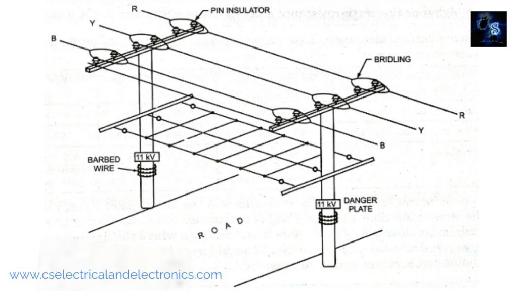
Various guarding arrangements are shown below.
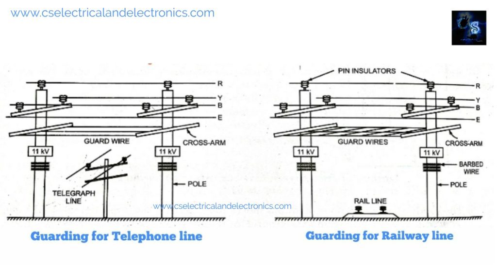
Cradle guarding is provided when the conductors are in horizontal or delta formation as in the case of 11 KV lines. The cradle guard is directly connected to an earth wire. If a line conductor breaks, it will fall on the guard, thereby blowing the fuse or tripping the coil of a circuit breaker When an lt line crosses a road or a railway line it is in the horizontal formation and therefore, at such places cradle guard is provided for lt lines also.
Cage guarding is provided on lt lines with vertical formation. The guard should be made of the same material as used for earth wire. In lt lines, the guard is connected with the neutral and insulated from the earth by means of a porcelain reel. In case a live conductor breaks it comes in contact with the guard which causes a short-circuit between the live conductor and Neutral causing the fuse to blow or the circuit breaker to trip.
3. Every tapping point or a dead end and angle of deviation requires a stay or strut.
4. As per IE rule, No 77 and 80 minimum clearance to the ground must be provided.
5. The D.P Structure must be provided for each KM run of the line where anchoring can be done. Additional anchoring is to be done in the middle for a straight run with two wind guys on either side using double strain or disc insulators ( so that each conductor breaking will be at 0.5 KM).
6. A tapping structure is to be provided for new lines that will have GOS for the disconnecting line mechanically and D.O.L.O cutouts for the protection of the line.
What is the LT line Or Low Tension Line?
The main function of the LT line is to transmit electricity from the distribution transformer to utilize. LT lines are those lines where the service mains are tapped. The LT line carries four wires one is neutral and the other three are a phase.
The voltage in LT lines is 440 volts between phases and 230 volts between neutral and phase. LT lines are drawn in every street of cities whereas HT lines are drawn on main roads only.
Construction Of LT Line
After a continuous survey of the LT line proposed route alignment of the LT, the line is to be done avoiding deviation as much as possible in a suitable ground without hard rock. The span ( distance between two poles) of the LT line is usually 65 meters for 8-meter poles.
At dead ends, deviations, and at anchoring points, only R.C.C poles are to be used, and elsewhere P.C.C poles can be used. Guys or Struts are to be provided for dead ends and also at deviation points to relieve the strain.
Anchoring (Breaking the line for stringing purposes) must be done for each 0.5 KM by providing double guy sets and having a strain insulator on both sides of all the 4-wire. Guarding is to be provided in case of crossing the line with road, telephone line, railway line, etc.
Materials Used In Construction Of LT Line

1. Poles
Poles are used to give support to the conductors which are drawn above the pole.
- The material used: R.C.C or P.C.C
- Length of Pole: 7.5 or 8 meter
- Working load: 115 or 140 kg
- C.C of proportion 1:2:3 with tor steel with M.S round for R.C.C
- C.C of proportion 1:2:3 with HT steel for P.C.C
2. Cross Arm
This gives support to the pin insulators, pin insulators are placed on a cross arm.
- Type: 2 pin ( to carry two wires)
- Name of material: M.S angle of 510 mm * 50 mm * 6 mm
- Type; 4 pins ( to carry four wires)
- Name of material: M.S angle 1200 mm * 50 mm * 6 mm suitable for LT and HT of 3-phase 4-wire lines.
3. Guy sets
- Class: 1.1 KV
- Stay wire used: 7 to 10 SWG standard stay wire with anchor and anchor plate, 8 No. strain insulator, 7/11 or 7/12 stay wire, stay complete clamp set.
4. Pin Insulator
- Class: 1.1 KV
- Material: Porcelain
- Size: 110 mm dia, height 110 mm with pin nut and washer complete.
5. Strain insulator
- Material: porcelain
- Number: 8 No
- Voltage Grade: 1.1 KV
6. Conductor
- Size: Squirrel ( ACSR No. 4) of 6/1/2.11 mm
- ( 6 aluminum conductors and one steel conductor of diameter 2.11 mm)
- Wren ( ACSR No. 8 ) of 6/1/1.33 mm
- Weasel ( ACSR No. 2 ) of 6/1/2.59 mm
I hope this article may help you all a lot. Thank you for reading. If you have any doubts regarding this article comment below.
Also, read:
- 10 Tips To Maintain Battery For Long Life, Battery Maintainance
- 10 Tips To Save Electricity Bills, Save Money By Saving Electricity
- 100 (AI) Artificial Intelligence Applications In The Automotive Industry
- 100 + Electrical Engineering Projects For Students, Engineers
- 100+ Indian Startups & What They Are Building
- 1000+ Automotive Interview Questions With Answers
- 1000+ MATLAB Simulink Projects For MTech, Engineering Students
- 2024 Is About To End, Let’s Recall Electric Vehicles Launched In 2024