Hello guys, welcome back to my blog. In this article, I will discuss what is PLC, the Programmable logic controller, examples or applications of PLC, working of the programmable logic controller, parts of PLC, advantages of using PLC, what is ladder logic in PLC.
If you have any doubts related to electrical, electronics, and computer science, then ask questions. You can also catch me on Instagram – CS Electrical & Electronics And Chetan Shidling.
Also, read:
- What Is DPF In A Vehicle, Diesel Particulate Filter, Purpose, Working
- Fuel Cell Working, Applications, Types, Advantages, Disadvantages
- Top Electric Drives Projects Lists For MTech & Engineering Students
What Is PLC, Programmable Logic Controller
A Programmable Logic Controller (PLC), additionally referred to as a programmable controller, is the identity given to a kind of device often used in business and industrial manipulation applications.
PLCs range from workplace computer systems in the kinds of duties that they operate the hardware and software program they require to operate these tasks. While the unique purposes range widely, all PLCs reveal inputs and different variable values, make selections primarily based on a saved program, and manipulate outputs to automate a system or machine. PLC is an industrial computer control system that constantly observes the condition of input devices and causes decisions based upon a custom program to manage the state of output devices.
This direction is intended to furnish you with simple records on the features and configurations of PLCs with emphasis on the S7-200 PLC family.
Working Of PLC Or Programmable Logic Controller
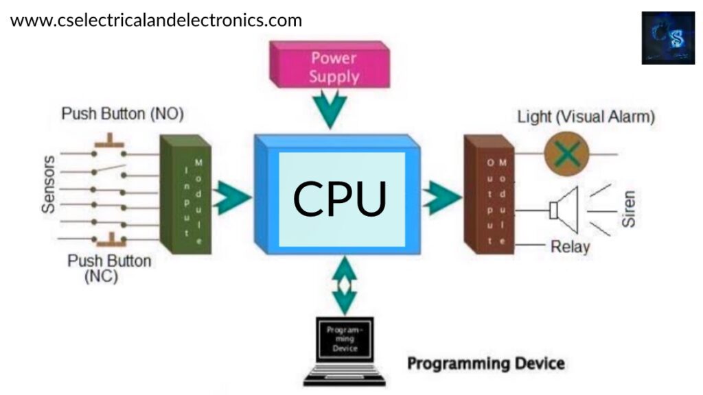
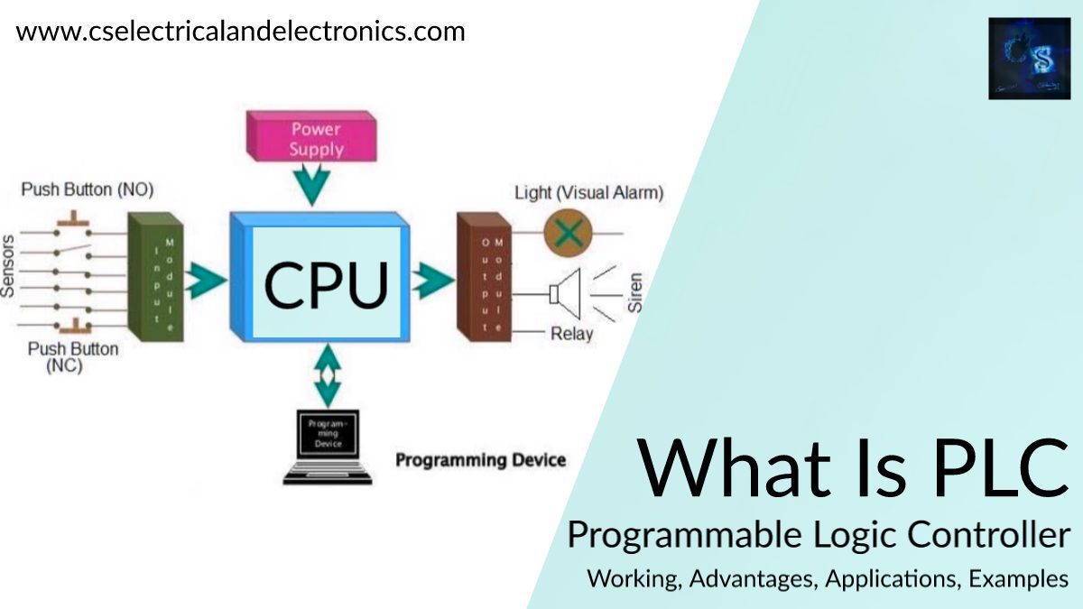
The fundamental factors of a PLC consist of input modules or points, a Central Processing Unit (CPU), output modules or points, and a programming device. The kind of input modules or factors used through a PLC relies upon the kinds of input gadgets used. Some input modules or factors reply to digital inputs, additionally referred to as discrete inputs, which are both on or off. Other modules or inputs reply to analog signals.
The essential feature of a PLC’s input circuitry is to convert the indicators supplied with the aid of these a range of switches and sensors into common-sense indicators that can be used by means of the CPU. The CPU evaluates the fame of inputs, outputs, and different variables as it executes a saved program. The CPU then sends alerts to replace the popularity of outputs.
The programming system is used to enter or trade the PLC’s software or to display or exchange saved values. Once entered, the application and related variables are saved in the CPU. In addition to these primary elements, a PLC device can also additionally contain an operator interface gadget of some kind to simplify monitoring of the laptop or process.
Parts Of PLC
01. CPU Or Processor
The Central Processing Unit, or principal processor, is a microprocessor-based system. It executes the manipulate application after studying area input status, then sends out instructions to subject outputs.
02. I/O Section
I/O modules act as the Real Data Interface between area and CPU. A PLC is aware of the actual repute of field devices and controls them with applicable I/O cards.
03. Programming Device
CPU cards can be linked with programming gadgets via a communication link by means of a programming port on the CPU. Operating station: An working station is used to grant an “operating window” to the PLC process. It is commonly a separate device, like a PC, that is loaded with Human Machine Interface Software.
Advantages Of PLC
- Smaller bodily measurement than hard-wire solutions.
- Easier and quicker to make changes.
- PLCs have built-in diagnostics and override functions.
- Diagnostics are centrally available.
- Applications can be straight away documented.
- Applications can be duplicated quickly and much less expensively.
Examples/applications of PLC
- Automatic car-washing system
- Traffic light system
- Industrial automation applications like bottle filling, food packeting, various types of motor control, etc.
- Elevator control
- Star-Delta operation of motor
What is Ladder Logic in PLC?
Ladder diagram, higher regarded as ladder logic, is a programming language used for PLCs (programmable common logic controllers). Programmable common logic controllers or PLCs are digital computer systems used to function manipulate functions, typically for industrial applications. Of the more than a few languages one can use to apply a PLC, ladder logic is the solely one immediately used to designed software for programmable logic controllers (PLCs) used in industrial control applications after electromechanical relay systems.
It makes use of lengthy rungs laid out between two vertical bars representing device power. Along the rungs are contacts and coils, modeled after the contacts and coils determined on mechanical relays. The contacts act as inputs and regularly characterize switches or push-buttons; the coils behave as outputs such as a mild or a motor.
Outputs do not have to be physical, though, and can characterize a single bit in the PLC’s memory. This bit can then be used later on in the code as some other input. Contacts are positioned in the collection to characterize AND common logic and in parallel when the use of OR logic. As with actual relays, there are commonly open contacts and typically closed contacts.
This was about “What Is PLC, Programmable Logic Controller“. I hope this article may help you all a lot. Thank you for reading.
Also, read:
- 10 Tips To Maintain Battery For Long Life, Battery Maintainance
- 10 Tips To Save Electricity Bills, Save Money By Saving Electricity
- 100 (AI) Artificial Intelligence Applications In The Automotive Industry
- 100 + Electrical Engineering Projects For Students, Engineers
- 100+ Indian Startups & What They Are Building
- 1000+ Automotive Interview Questions With Answers
- 1000+ MATLAB Simulink Projects For MTech, Engineering Students
- 2024 Is About To End, Let’s Recall Electric Vehicles Launched In 2024