Hello guys, welcome back to our blog. Here in this article, we will discuss what MIL (module in the loop), SIL (software in loop), HIL (hardware in the loop), and PIL (processor in the loop) in MATLAB Simulink are, and what the importance of MIL, SIL, HIL, and PIL.
If you have any electrical, electronics, and computer science doubts, then ask questions. You can also catch us on Instagram – CS Electrical & Electronics.
Also, read:
- Types Of Temperature Sensors Used In Circuit With Explanation
- Applications Of Artificial Intelligence (AI) In Renewable Energy
- World’s First Flying Bike Creates Its Debut In United States Auto Dramatization
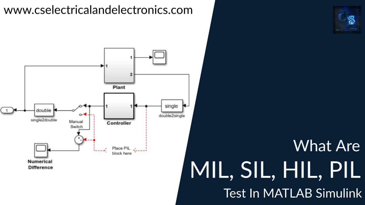
What MIL, SIL, HIL, And PIL In MATLAB Simulink Are
The creation of requirements, design, analysis, verification, and validation of complex systems, particularly cyber-physical systems and systems of systems, are supported by model-based systems engineering (MBSE).
The two main components of MBSE are validation (testing) and verification (simulation). To guarantee a solid and trustworthy outcome, the MBSE process includes specific points where simulation and testing for the model in the loop (MIL), software in the loop (SIL), the processor in the loop (PIL), and hardware in the loop (HIL) are conducted.
Models in MBSE are digital simulations of many system components, including electrical, electronic, mechanical, hydraulic, optical, etc. MBD uses simulation to foretell how a physical system or system component will operate when it is eventually built.
Initially, the controlled system, the emulated hardware, or the software environment were referred to as being “in-the-loop.” These days, it more frequently refers to the entire models of software, hardware, and physical system.
The digital twin of the ultimate system is made up of the merged models of the various system components. As part of a larger MBSE effort, MIL, SIL, PIL, and HIL simulation and testing are frequently employed successively to confirm the outcomes of the MBD process. It may be necessary to return to the previous MBD step until the required result is obtained if a simulation fails to produce the desired result or if the requirements are changed.
After you have identified the requirements for the component or system you are building and they have been modeled at the simulation level, MIL, SIL, PIL, and HIL testing are included in the verification element of the Model-Based Design process (e.g. Simulink platform).
A few verification processes are carried out before the model is deployed to the hardware for production; these are described below. I’ll use constructing a controller for a DC motor as an example and place the code made from the controller model in a System-on-Chip that supports it.
01. Model-Based Testing Or Model-in-the-Loop (MIL) simulation
To begin, you must create a model of the actual hardware (plant) in a simulation environment like Simulink, which captures the majority of the crucial aspects of the hardware system. Develop the controller model after the plant model has been made, then test it to see if it can control the plant—in this case, the model of the motor—according to the specifications.
Model-in-Loop (MIL) is a process step where the controller logic is tested using a simulated model of the plant. If your controller performs as expected, you should document the controller’s input and output for use in a later stage of verification.
02. Software-in-the-Loop (SIL) simulation
The next stage is Software-in-Loop (SIL), where you produce code exclusively from the controller model and replace the controller block with this code. This is done after your model has been verified in MIL simulation.
Run the simulation after that using the Plant, which is still the software model, and the Controller block (which contains the C code) (similar to the first step). This stage will help you determine whether your control logic or the Controller model, can be turned into code and whether it can be implemented on hardware.
This is where you should record the input-output and compare it to what you accomplished in the previous phase. If you notice a significant difference in them, you might need to return to MIL and make the appropriate adjustments before repeating steps 1 and 2. You can proceed to the following stage if your model has passed the SIL test and the performance was satisfactory.
03. Processor-in-the-Loop (PIL) or FPGA-in-the-Loop (FIL) simulation
Processor-in-the-Loop (PIL) testing is the following phase. In this stage, we’ll load the Controller model onto an embedded processor and use the simulated Plant to execute a closed-loop simulation.
Therefore, the Controller Subsystem will be replaced with a PIL block that will run the Controller code on the hardware. This step will enable you to determine whether the processor can execute the developed Control logic. If there are errors, go back to your code, whether it’s SIL or MIL, and fix them.
The simulation is known as FPGA-in-the-Loop when it is executed on an FPGA rather than an embedded processor.
04. Hardware-in-the-Loop (HIL) Simulation
You can use a real-time system like Speedgoat to run the simulated plant model before connecting the embedded CPU to the actual hardware. The real-time system runs deterministic simulations and is physically connected to the embedded processor via interfaces like CAN and UDP as well as analog inputs and outputs.
This can assist you in identifying problems with the I/O interface and communication channels, such as attenuation and delay produced by analog channels that might cause the controller to become unstable. Simulating this behavior is not possible. HIL testing is typically carried out for safety-critical applications and is mandated by validation standards for the automotive and aerospace industries.
05. Actual Hardware
After your plant model has been confirmed using PIL, you can now swap it out for the original hardware, such as the lab model, and conduct a test. Consider a DC motor with a speed controller that is currently being developed; the controller is then implemented in an FPGA or processor and interfaced to the DC motor by connecting the inputs and outputs/states at the appropriate locations for sensors and transducers.
Conclusion:
Large-scale software projects were the first target audience for the development of MIL, SIL, PIL, and HIL testing and simulation. These days, they are also used in conjunction with the other MBSE components to build intricate cyber-physical systems and systems of systems.
Throughout the entire software and system life cycle, the combination of MBD and MBSE contributes in a variety of ways to shortened development times and enhanced system performance.
This was about “What MIL, SIL, HIL, And PIL In MATLAB Simulink Are“. I hope this article may help you all a lot. Thank you for reading.
Also, read:
- 10 Free ADAS Projects With Source Code And Documentation – Learn & Build Today
- 10 Tips To Maintain Battery For Long Life, Battery Maintainance
- 10 Tips To Save Electricity Bills, Save Money By Saving Electricity
- 100 (AI) Artificial Intelligence Applications In The Automotive Industry
- 100 + Electrical Engineering Projects For Students, Engineers
- 100+ Indian Startups & What They Are Building
- 1000+ Automotive Interview Questions With Answers
- 1000+ Electronics Projects For Engineers, Diploma, MTech Students