Hello guys, welcome back to my blog. This article will be on speed control methods for different motors such as AC motors, DC motors, and I will give a short explanation on all types of speed control methods for motors.
If you have any electrical, electronics, and computer science doubts, then ask questions. You can also catch me on Instagram – CS Electrical & Electronics And Chetan Shidling.
Also, read:
- Top 10 Types Of Testing On Electrical Motors, Electrical Motor Testing
- Top 10 Fuel Cell Manufacturing Companies In The World In 2022
- Top 22 MATLAB Simulink Interview Questions And Answers
Speed Control Methods For Different Motors
Speed Control Methods of DC Motor
Speed Control of Shunt Motor:
01. Flux Control Method
A rheostat is connected in series with the field winding to regulate the flux. Increasing the resistance in series with the field winding raises the speed while lowering the flux. Because the field current in shunt motors is so low, Ish2 * R loss is minimal. As a result, this strategy is highly effective. Although speed may be increased above the stated amount by lowering flux, this approach places a limit on maximum speed since field flux weakening beyond a certain point would negatively affect commutation.
02. Armature Control Method
The back emf Eb is directly related to the speed of a dc motor, and Eb = V – IaRa. That is, if the supply voltage V and armature resistance Ra are constant, the speed is proportional to the armature current (Ia). As a result, when we increase resistance in series with the armature, Ia lowers, and the speed decreases as well. The lower the speed, the larger the resistance in series with the armature.
03. Voltage Control Method
a. Multiple voltage control:
The shunt field is coupled to a set exciting voltage in this approach, and the armature is supplied with various voltages. With the use of appropriate switchgear, the voltage across the armature may be altered. The voltage across the armature is roughly proportional to the speed.
b. Ward-Leonard System:
This technique is employed when precise motor speed control is required (e.g electric excavators, elevators, etc.). The output from the generator is sent to the armature of the motor whose speed is to be regulated in this fashion. The field regulator on the generator allows it to vary its output voltage from zero to its maximum value, allowing the armature voltage of the motor to be altered extremely smoothly. As a result, this technology may provide highly smooth dc motor speed control.
Speed Control Of Series Motor:
01. Flux Control Method
a. Field diverter: Parallel to the series field, a variable resistance is attached. This variable resistor is known as a diverter because it may redirect the desired amount of current via it, lowering the current through the field coil. As a result, flux may be reduced to the required level while speed is enhanced.
b. Armature diverter: The armature is linked to the diverter. If the armature current is lowered for given fixed load torque, the flux must increase, as Ta Ia. As a result, more current will be drawn from the supply, causing the flux to rise and, the motor’s speed to drop.
c. Tapped field control: The number of turns on the field coil is divided. As a result, we may choose a different value of simply changing the number of turns.
d. Paralleling field coils: By regrouping coils in this technique, several speeds may be achieved.
02. Variable Resistance In Series With Armature
The voltage across the armature can be decreased by adding resistance in series with it. As a result, speed decreases in direct proportion to it.
03. Series-Parallel Control
When two or more mechanically connected series motors are utilized in electric traction, this system is extensively used. The motors are coupled in series for low speeds and parallel for greater speeds. When the motors are connected in series, the current flowing through them is the same, but the voltage across each motor is split. When two motors are connected in parallel, the voltage across each is the same, but the current is split.
Speed Control Methods Of AC Motor
Induction Motor Speed Control From Stator Side:
01. By Changing The Applied Voltage
From the torque equation of induction motor,
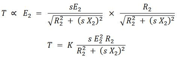
The rotor resistance R2 is constant, and if the slip s is minor, then (sX2)2 can be ignored. As a result, T sE2, where E2 is the rotor induced emf and E2 V is the rotor voltage.
As a result, T sV2 indicates that as the supply voltage is reduced, the produced torque drops. As a result, for the same load torque, the slip rises as the voltage lowers, and the speed reduces as a result.
02. By Changing The Applied Frequency
The synchronous speed of an induction motor’s revolving magnetic field is given by,
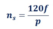
where f is the supply frequency and P is the number of stator poles
As a result, the synchronous speed changes as the supply frequency changes. N = Ns is the actual speed of an induction motor (1 – s). This approach, however, is not extensively employed. It can be utilized in situations when the induction motor is powered by a separate generator (so that frequency can be easily varied by changing the speed of the prime mover). The motor current may also become excessively high at lower frequencies owing to decreasing reactance. When the frequency is raised over the rated value, the maximum torque created decreases while the speed increases.
03. Constant V/F Control Of Induction Motor
This is the most common way of managing an induction motor’s speed. The air gap flux will tend to saturate if the supply frequency is lowered while retaining the rated supply voltage. This will result in excessive stator current and flux wave distortion. As a result, the stator voltage should be proportional to the frequency to keep the air-gap flux constant. The ratio of the stator voltage and frequency determines the magnitude of the stator flux.
As a result, if the voltage-to-frequency ratio remains constant, the flux remains constant. Keeping V/F constant also keeps the produced torque close to constant. This technique is more efficient in terms of runtime. As a result, for speed control, the vast majority of AC speed drives use the constant V/F method (or variable voltage, variable frequency method). This approach has a soft start’ feature in addition to a wide range of speed control.
04. Changing The Number Of Stator Poles
The number of stator poles may be altered to modify synchronous speed (and hence running speed). Because the squirrel cage rotor adjusts to any number of stator poles, this approach is commonly utilized for squirrel cage induction motors. Two or more independent stator windings wound for different numbers of poles in the same slots change the stator poles.
Induction Motor Speed Control From Rotor Side:
01. Rotor Rheostat Control
This approach is comparable to how a DC shunt motor’s armature rheostat is controlled. However, this approach is only relevant to slip-ring motors since squirrel cage motors do not allow for the inclusion of external resistance in the rotor.
02. Cascade Operation
Two motors are employed in this form of speed control. Both are connected to the same shaft and run at the same pace. One motor is powered by a three-phase supply, while the other is powered by the induced emf in the first motor through slip-rings.
03. By Injecting EMF In Rotor Circuit
The speed of an induction motor is adjusted in this way by introducing a voltage into the rotor circuit. The voltage (emf) that is injected must have the same frequency as the slip frequency. The phase of injected emf, on the other hand, is unrestricted. Rotor resistance will be enhanced if we inject emf that is in phase with the rotor-produced emf. Rotor resistance will be reduced if we inject emf that is in phase with the rotor-produced emf. Speed may be regulated by adjusting the phase of the injected emf. The major benefit of this technology is that it allows for a wide range of speed control (both above and below average). Various systems, such as the Kramer system and the Scherbius system, can be used to inject the emf.
This was about “Speed Control Methods For Different Motors“. I hope this article “Speed Control Methods For Different Motors” may help you all a lot. Thank you for reading.
Also, read:
- 10 Tips To Maintain Battery For Long Life, Battery Maintainance
- 10 Tips To Save Electricity Bills, Save Money By Saving Electricity
- 100 (AI) Artificial Intelligence Applications In The Automotive Industry
- 100 + Electrical Engineering Projects For Students, Engineers
- 100+ Indian Startups & What They Are Building
- 1000+ Automotive Interview Questions With Answers
- 1000+ MATLAB Simulink Projects For MTech, Engineering Students
- 2024 Is About To End, Let’s Recall Electric Vehicles Launched In 2024