Hello guys, welcome back to my blog. In this article, I will discuss the types of cell balancing topologies, active and passive cell balancing topologies, and I will also discuss which cell balancing topologies are best for real-world applications.
If you have any doubts related to electrical, electronics, and computer science, then ask question. You can also catch me @ Instagram – Chetan Shidling.
Also, read:
- What Is Battery Management System, Working, Advantages Of BMS
- Top And Bottom Cell Balancing Using A Flyback Converter Balancing
- Different Types Of Batteries, Advantages, Disadvantages, Applications
Types Of Cell Balancing Topologies
Battery management systems (BMSs) are an essential component of the battery arrangement in electric vehicles (EVs) and (HEV) hybrid electric vehicles (HEVs). The purpose of the BMS is to preserve the battery system from damage, foretell and improve batteries life, and manage the battery system in an accurate and safe operational situation.
The BMS presents different tasks, such as measuring the system temperature (VIT), voltage, and current the cells’ state of health (SoH), state of charge (SoC), and remaining useful life (RUL) determination, preserving the cells, thermal supervision, monitoring, controlling the charge/discharge procedure, collecting historical data, data acquisition, communication with on-board and off-board modules (maybe charger), and several importantly is the cell balancing.
Battery systems are influenced by various circumstances, a key one being the cells unbalancing. The inequality of cells in a battery pack is a vital factor influencing battery system life. Without a balancing system, the individual cell voltages will ride apart over time. The capacity of the total load will also reduce more immediately during operation and the battery system will fail early. Thus, cell balancing is essential for protecting battery life.
Types Of Cell Balancing Topologies
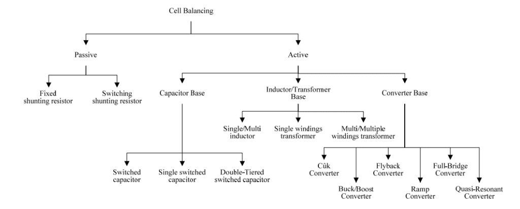
These are the types of cell balancing topologies, let me first explain what is active and passive cell balancing and then I will start explaining its types.
Active cell balancing involves making the state of charge of each cell equal without wasting or dissipating energy through a resistor. Here the energy is carried from one cell to another cell, from cell to the battery pack, or from battery pack to cell. Passive cell balancing involves making the state of charge of each cell equal by wasting or dissipating energy through a resistor.
Passive Cell Balancing Topologies
01. Fixed shunting resistor:
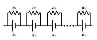
This method balances every cell voltage by connecting the fixed or set resistor in parallel with all series-connected cells based on the necessary cell balance current. The balancing current is wasted or dissipated through the resistor which restricts the voltage of every cell.
This fixed shunt resistor system is essentially utilized in lead-acid and nickel battery uses or applications. This fixed shunt resistor circuit needs low cost because its structure is simple. But, energy utilized by those resistors for balancing a battery may occur in thermal losses in the BMS or battery management system. Hence, this fixed shunting resistor system is an ineffective cell balancing circuit.
02. Switching shunting resistor:
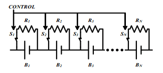
This cell balancing system is currently the usual conventional way in the cell equalizing method. This system is split into a continuous mode and a sensing mode. At the continuous method, every switch is controlled to be switched on or switched off at the same time. When a resistor value is well selected at this mode, it is effective to charge the whole battery.
In the sensing method, this approach needs a real-time voltage sensor for every cell. This cell balancing circuitry also utilizes high power via a balancing resistor. Because of this feature, thermal losses may occur from high currents by balancing switches and resistors. Hence, cell thermal management is also needed to manage the thermal losses. This cell balancing circuitry is proper for a battery system that needs a low current when it is charged or discharged.
Active Cell Balancing Topologies
01. Capacitor Base:
An active cell balancing circuitry based on capacitors levels cells with capacitors by carrying unequal energy among multiple cells in the battery line. At a specific cell, voltage is below a capacitor voltage, the cell is charged by the capacitor. In reverse, if a particular cell voltage is greater than a capacitor voltage, the cell is discharged to the capacitor.
In different terms, a charged capacitor by a greater energy cell than others discharges its power to a comparatively lower energy cell. Because energy is carried from cells by capacitors, thermal losses of this cell balancing circuitry are normally lower than the of a passive cell balancing method. But, this equalizing circuit needs a complicated switch structure and a complex control method for a switch.
a. Single switched capacitor:
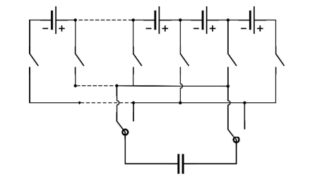
An active cell balancing circuit by a single capacitor consists of an N quantity of cells (B1 ~ BN), N + 2 quantity of switches (S1 ~ SN+2), plus one capacitor (C) in the cell balancing circuit. A capacitor in the battery line is discharged or charged in sequence to balance every cell. The cell balancing circuit is easy because it utilizes a single capacitor despite the number of cells attached to the battery line. But, this cell balancer needs a huge number of switches and smart control of the switches.
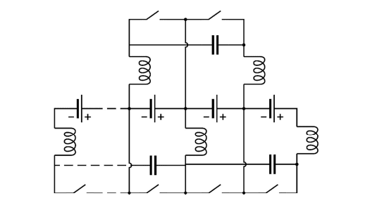
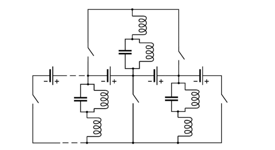
b. Double tiered switched capacitor:
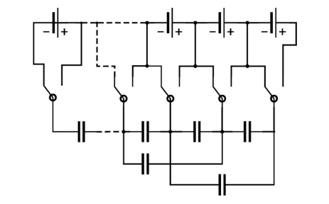
An active cell balancing circuit with multiple capacitors transfers unequal cell energy by multiple capacitors. This cell balancer is composed of N quantity of cells (B1 ~ BN), switches (S1 ~ SN), and N-1 quantity of capacitors (C1 ~ CN-1) in the cell balancing circuitry. In this circuit, capacitors for balancing unequal cell energy are connected to all batteries. The double-tiered switched capacitor equalizer is an advance on the standard capacitor equalizer. The topology utilizes the second level of capacitors which now pass energy to be carried between every two cells and not only neighboring cells.
02. Inductor/Transformer Base:
A cell balancing circuit explained in this part balances battery cells by magnetic elements, such as inductors or transformers, by carrying unequal energy among multiple cells. The cell balancer results in all cells being leveled by carrying unbalanced cell energy from a higher energy cell to the lower energy cell in the battery box by inductors or transformers.
The balancing time of the cell balancing circuitry can reduce by a high cell balancing current. But, this cell balancing circuit needs high production cost, and a magnetic transformer loss should be taken or consider during the design phase of the cell balancer. Because its switching frequency is normally high, every cell in the battery line should have a filtering capacitor.
a. Single/Multi inductor:
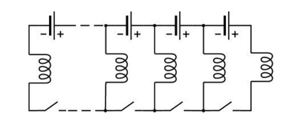
The controller algorithm of this cell equalizing circuit by single or multiple inductors is that it identifies each cell voltage and decides a cell to transfer power. When MOSFETs are switched on and switched off, unbalanced cell energy is passed to an inductor. In this circuit, unbalanced cell energy is carried from a higher energy cell to a lower power cell in the battery line by an inductor.
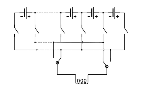
b. Single transformer:
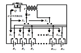
An active cell balancing circuitry based on a single transformer method that includes a MOSFET, a diode (D), a transformer (T), and N+2 quantity of switches (S1 ~ SN+2) and N quantity of battery cells (B1 ~ BN)11. This cell balancing system with a single transformer has two topologies: the 1st one is a pack-to-cell method, and the 2nd one is a cell-to-pack method. This cell balancer has a fast balancing rate with fewer magnetic losses. But, this cell equalizer needs accurate switch control.
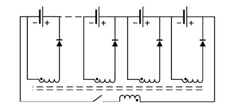
c. Multiple winding transformer:
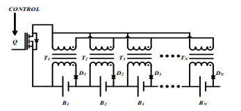
An active cell balancing circuitry with multiple transformers is made of N quantity of cells (B1 ~ BN), diodes (D1 ~ DN), transformers (T1 ~ TN), and a single MOSFET. The control system of this cell matching circuit is simple because this circuit only utilizes a single switch. Along with this, the balancer has a fast balancing speed. But, it needs a high cost and complex circuit and should stop the transformer from being saturated.
03. Converter Base
This active cell balancing circuitry balances unbalanced cell power in the battery line by a DC-DC converter so as a flyback converter either forward converter. The construction of a balancer with a flyback converter topology holds the primary and secondary sides based on its transformer. The cell balancer discharges or charges unbalanced cell energy by a transformer which gives an insulated construction with reliable energy transmission. This topology is classified as,
a. Cuk converter:
The Ćuk converter is a kind of buck-boost converter with zero ripple current. Ćuk converter can be viewed as a blend of the boost converter and buck converter, having one switching equipment and a mutual capacitor, to couple the power or energy.
b. Forward converter:
The forward converter is a conventional transformer-based DC to DC converter. This cell equalizer utilizes a specific multi-primary single secondary transformer. The arrangement can also utilize many single primary single secondary transformers. The forward converter equalizer works by stimulating the greatest potential cell over the set voltage threshold to decrease the cell charge through balancing the stack.
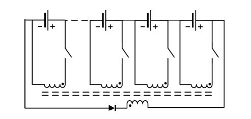
c. Flyback converter:
A cell balancer by a flyback converter topology consists of N quantity of cells (B1 ~ BN), a transformer (T), diodes (D1 ~ DN), and a single MOSFET. In this cell equalizer, the power of a high voltage cell is collected in the transformer. When the secondary side switch is set on, this power is carried to the lower voltage cells by the diodes (D1 ~ DN). The cell balancing system can be easily achieved in a great number of cells and is usually used for EVs. But, there is a magnetic waste problem in the multi-winding transformer.
d. Ramp converter:
e. full-bridge converter:
This cell equalizer with a full-bridge converter works with the following two methods: “buck mode” and “boost mode”. This system is generally utilized in almost all high-power systems so as plugin hybrid electric (PHEV) and energy storage methods (ESM). The cell balancing system has quick equalization speed and high productivity. But, the price of this cell balancer is high, and its control system is complicated.
f. Quasi-resonant converter:
The Quasi-Resonant Zero Current Switching (QRZCS) balancer is a DC-DC converter-based cell balancer. The method of the QRZCS topology is identical to the buck-boost topology except with the extension of the resonant circuit. The QRZCS balancer is also the usually complicated equalizer because of the huge number of components and the complicated control of the converter.
This was about different types of cell balancing topologies. I hope this article “Types Of Cell Balancing Topologies” may help you all a lot. Thank you for reading.
Also, read:
- 10 Free ADAS Projects With Source Code And Documentation – Learn & Build Today
- 10 Tips To Maintain Battery For Long Life, Battery Maintainance
- 10 Tips To Save Electricity Bills, Save Money By Saving Electricity
- 100 (AI) Artificial Intelligence Applications In The Automotive Industry
- 100 + Electrical Engineering Projects For Students, Engineers
- 100+ Indian Startups & What They Are Building
- 1000+ Automotive Interview Questions With Answers
- 1000+ Electronics Projects For Engineers, Diploma, MTech Students