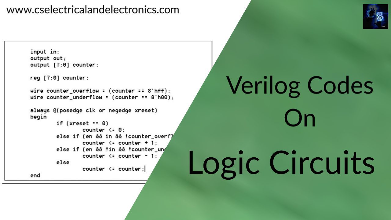
Hello guys, welcome back to my blog. In this article, I will share Verilog codes on different digital logic circuits, programs on Verilog, codes on adder, decoder, multiplexer, mealy, BCD up counter, etc.
If you have any doubts related to electrical, electronics, and computer science, then ask question. You can also catch me @ Instagram – Chetan Shidling.
Also, read:
- What Is FPGA, Field Programmable Gate Array, FPGA Tools
- Top 50+ Interview Questions And Answers On VLSI CMOS Circuits
- How Chips Are Made Or Manufactured, How Integrated Circuit Are Formed
Verilog Codes On Different Digital Logic Circuits
01. Verilog code on Mealy.
module mealyprog_tb;

	// Inputs
	reg CLK;
	reg RST;
	reg x;

	// Outputs
	wire z;

	// Instantiate the Unit Under Test (UUT)
	mealyprog uut (
		.CLK(CLK),
		.RST(RST),
		.x(x),
		.z(z)
	);

	initial begin
		// Initialize Inputs
		CLK = 0;
		RST = 0;
		x = 0;

		// Wait 100 ns for global reset to finish
		#100;

		// Add stimulus here
 #10 x=1;
  #10 x=0;
  #10 x=0;
  #10 x=1;
  #10 x=1;
  #10 x=0;
  #10 x=1;
  #10 x=0;
  #10 x=0;
  #10 x=0;
  #10 x=1;
  #10 x=1;
	end
   always @(x)
begin
forever #5 CLK=~CLK;

end
endmodule
Test Bench:
module mealyprog_tb;

	// Inputs
	reg CLK;
	reg RST;
	reg x;

	// Outputs
	wire z;

	// Instantiate the Unit Under Test (UUT)
	mealyprog uut (
		.CLK(CLK),
		.RST(RST),
		.x(x),
		.z(z)
	);

	initial begin
		// Initialize Inputs
		CLK = 0;
		RST = 0;
		x = 0;

		// Wait 100 ns for global reset to finish
		#100;

		// Add stimulus here
 #10 x=1;
  #10 x=0;
  #10 x=0;
  #10 x=1;
  #10 x=1;
  #10 x=0;
  #10 x=1;
  #10 x=0;
  #10 x=0;
  #10 x=0;
  #10 x=1;
  #10 x=1;
	end
   always @(x)
begin
forever #5 CLK=~CLK;

end
endmodule
02. Verilog code on BCD up counter or binary-coded decimal up counter.
module bcd_upcounter(clk,reset,count);
output reg [3:0] count=0;
input wire clk,reset;
reg updown=0;

always @ (posedge clk)
begin
if(reset)
count<=0;
else if(updown==0&&count<15)
begin
count<=count+1;
end
if(count==15)
updown=1;
if(updown==1&&count>0)
count<=count-1;
else
count=0;
end
endmodule
Test Bench:
module bcdupcounter_tf;

	// Inputs
	reg clk;
	reg reset;

	// Outputs
	wire [3:0] count;

	// Instantiate the Unit Under Test (UUT)
	bcd_upcounter uut (
		.clk(clk),
		.reset(reset),
		.count(count)
	);

	initial begin
		// Initialize Inputs
		forever #10 clk=~clk;
		end
		initial begin
		clk = 0;
		reset = 0;
		end

		initial begin
		//updown=0;
		#200;
		reset=0;
		//updown=1;
		#350;
		reset=1;
	end

endmodule
03. Verilog code on Binary to Excess-3 conversion.
module Bin_excess(b,e);
input [2:0] b;
output wire [2:0] e;
assign e[2]=b[0]|b[1]|b[2];
assign e[1]=b[2]|~(b[1]^b[0]);
assign e[0]=~b[0];
endmodule
Test Bench:
module BIN_EXCESS3_tb;

	// Inputs
	reg [2:0] b;

	// Outputs
	wire [2:0] e;

	// Instantiate the Unit Under Test (UUT)
	Bin_excess uut (
		.b(b),
		.e(e)
	);

	initial begin
		// Initialize Inputs
		b = 0;

		// Wait 100 ns for global reset to finish
		#100;

		// Add stimulus here

      b=3'b000;
		#100;
		b=3'b001;
		#100;
		b=3'b010;
		#100;
		b=3'b011;
		#100;

	end

endmodule
04. Verilog code on binary to gray conversion.
module BIN_GRAY(g,b);
input [2:0] b;  //3-bits 0,1,2
output wire [2:0] g;
assign g[2]=b[2];
assign g[1]=b[2]^b[1];
assign g[0]=b[1]^b[0];
Test Bench:
module bin_Gray_tb;

	// Inputs
	reg [2:0] b;

	// Outputs
	wire [2:0] g;

	// Instantiate the Unit Under Test (UUT)
	BIN_GRAY uut (
		.g(g),
		.b(b)
	);

	initial begin
		// Initialize Inputs
		b = 0;

		// Wait 100 ns for global reset to finish
		#100;

		// Add stimulus here
      b=3'b001;
		#100;
		b=3'b010;
		#100;
		b=3'b100;
		#100;

	end

endmodule
05. Verilog code on booth multiplier.
module booth_mul(a,b,c);
input signed [3:0] a,b;
output reg signed [7:0] c;
reg [1:0] temp;
integer i;
reg e;
reg [3:0] y1;
always @(a,b)
begin
c=8'd0;
e=1'd0;
for(i=0;i<4;i=i+1)
begin
temp={a[i],e};
y1=-b;
case(temp)
2'd2:c[7:4]=c[7:4]+y1;
2'd1:c[7:4]=c[7:4]+b;
default :begin end
endcase
c=c>>1;
c[7]=c[6];
e=a[i];
if(b==4'd8)
begin
c=-c;
end
end
end
endmodule
Test Bench:
module booth_tf;

	// Inputs
	reg [3:0] a;
	reg [3:0] b;

	// Outputs
	wire [7:0] c;

	// Instantiate the Unit Under Test (UUT)
	booth_mul uut (
		.a(a),
		.b(b),
		.c(c)
	);

	initial begin
		// Initialize Inputs
		a = 0;
		b = 0;
		#100;

		// Add stimulus here
      a = 2;
		b = 2;
		#100;
		a = 3;
		b = 4;
		#100;
	end

endmodule
06. Verilog code on a carry-lookahead adder.
module CLA_ADDER(cout,sum,a,b,cin);
input [3:0] a,b;
input cin;
output [3:0] sum;
output cout;
wire [3:0] g,p;
wire [3:0] c;
assign c[0]=cin;
assign g=a&b;
assign p=a|b;

assign c[1]=g[0]|p[0]&c[0];
assign c[2]=g[1]|p[1]&c[1];
assign c[3]=g[2]|p[2]&c[2];
assign cout=g[3]|p[3]&c[3];

assign sum=a^b^c;

endmodule
Test Bench:
module cla_adder_tb;

	// Inputs
	reg [3:0] a;
	reg [3:0] b;
	reg cin;

	// Outputs
	wire cout;
	wire [3:0] sum;

	// Instantiate the Unit Under Test (UUT)
	CLA_ADDER uut (
		.cout(cout),
		.sum(sum),
		.a(a),
		.b(b),
		.cin(cin)
	);

	initial begin
		// Initialize Inputs
		a = 0;
		b = 0;
		cin = 0;

		// Wait 100 ns for global reset to finish
		#100;

		// Add stimulus here
       a=4'b0001;;
		 b=4'b0001;
		 cin=1;
		 #100;
		  a=4'b0010;
		 b=4'b0010;
		 cin=1;

	end

endmodule
07. Verilog code on Decoder.
module DECODERS(m,s,en);
input [2:0] s;
input en;
output [7:0] m;
assign m[7]=(s[2]&s[1]&s[0])&en;
assign m[6]=(s[2]&s[1]&~s[0])&en;
assign m[5]=(s[2]&~s[1]&s[0])&en;
assign m[4]=(s[2]&~s[1]&~s[0])&en;
assign m[3]=(~s[2]&s[1]&s[0])&en;
assign m[2]=(~s[2]&s[1]&~s[0])&en;
assign m[1]=(~s[2]&~s[1]&s[0])&en;
assign m[0]=(~s[2]&~s[1]&~s[0])&en;
endmodule
Test Bench:
module DEcoders_tb;

	// Inputs
	reg [2:0] s;
	reg en;

	// Outputs
	wire [7:0] m;

	// Instantiate the Unit Under Test (UUT)
	DECODERS uut (
		.m(m),
		.s(s),
		.en(en)
	);

	initial begin
		// Initialize Inputs
	//	s = 0;
//		en = 0;

		// Wait 100 ns for global reset to finish
		//#100;

		// Add stimulus here
en=1;
s=3'b000;
#100;
s=3'b001;
#100;
s=3'b010;
#100;
s=3'b011;
#100;
s=3'b100;
#100;
s=3'b101;
#100;
s=3'b110;
#100;
s=3'b111;
#100;

	end

endmodule
08. Verilog code on Encoder.
module encoders(y,x,en);
input en;
input [7:0] x;
output [2:0] y;
assign y[2]=en&(x[4]|x[5]|x[6]|x[7]);
assign y[1]=en&(x[2]|x[3]|x[6]|x[7]);
assign y[0]=en&(x[1]|x[3]|x[5]|x[7]);
endmodule
Test Bench:
module Encoders_tb;

	// Inputs
	reg [7:0] x;
	reg en;

	// Outputs
	wire [2:0] y;

	// Instantiate the Unit Under Test (UUT)
	encoders uut (
		.y(y),
		.x(x),
		.en(en)
	);

	initial begin
		// Initialize Inputs
		x = 0;
		en = 0;

		// Wait 100 ns for global reset to finish
		#100;

		// Add stimulus here
en=1;
x=8'b00000001;
#100;
x=8'b00000010;
#100;
x=8'b00000100;
#100;
x=8'b00000100;

	end

endmodule
09. Verilog code on full adder using struct modeling.
module FA(a,b,cin,cout,S);
input a,b,cin;
output S,cout;
//declaring variables
wire C1,C2,S1,S2;
//initiata HA's
HA ha1(C1,S1,a,b);
HA ha2(C2,S2,S1,cin);
or r(cout,C1,C2);
endmodule

//for HA function
module HA(C1,S1,a,b);
input a,b;
output C1,S1;
xor S(S1,a,b);
and C(C1,a,b);
endmodule
Test Bench:
module FA_tb;

	// Inputs
	reg a;
	reg b;
	reg cin;

	// Outputs
	wire cout;
	wire S;

	// Instantiate the Unit Under Test (UUT)
	FA uut (
		.a(a),
		.b(b),
		.cin(cin),
		.cout(cout),
		.S(S)
	);

	initial begin
		// Initialize Inputs
		a = 0;
		b = 0;
		cin = 0;

		// Wait 100 ns for global reset to finish
		#100;

		// Add stimulus here
      a = 0;
		b = 0;
		cin = 1;
      #100;
		a = 0;
		b = 1;
		cin = 0;
      #100;
		a = 0;
		b = 1;
		cin = 1;
      #100;
	end

endmodule
10. Verilog code on a full adder.
module full_ADDER(sum,carry,a,b,c);
input a,b,c;
output sum,carry;
assign sum=a^b^c;
assign carry=a&b|b&c|c&a;

endmodule
Test Bench:
module FULL_ADDER_tf;

	// Inputs
	reg a;
	reg b;
	reg c;

	// Outputs
	wire sum;
	wire carry;

	// Instantiate the Unit Under Test (UUT)
	full_ADDER uut (
		.sum(sum),
		.carry(carry),
		.a(a),
		.b(b),
		.c(c)
	);

	initial begin
		// Initialize Inputs
		a = 0;
		b = 0;
		c = 0;

		// Wait 100 ns for global reset to finish
		#100;

		// Add stimulus here
		a = 0;
		b = 0;
		c = 0;
		#100;
		a = 0;
		b = 0;
		c = 1;
		#100;
		a = 0;
		b = 1;
		c = 0;
		#100;
		a = 1;
		b = 1;
		c = 1;
		#100;

	end

endmodule
11. Verilog code on gray to binary conversion.
module GRAY_BIN(g,b);
input [3:0] g;
output [3:0] b;
assign b[3]=g[3];
assign b[2]=g[3]^g[2];
assign b[1]=g[3]^g[2]^g[1];
assign b[0]=g[3]^g[2]^g[1]^g[0];
endmodule
Test Bench:
module Gray_BIn_tf;

	// Inputs
	reg [3:0] g;

	// Outputs
	wire [3:0] b;

	// Instantiate the Unit Under Test (UUT)
	GRAY_BIN uut (
		.g(g),
		.b(b)
	);

	initial begin
		// Initialize Inputs
		g = 0;

		// Wait 100 ns for global reset to finish
		#100;

		// Add stimulus here
		g=4'b1000;
		#100;
		g=4'b1001;
		#100;
		g=4'b1001;
		#100;
		g=4'b1010;
		#100;

	end

endmodule
12. Verilog code on gray to binary using inout.
module GRAY_BIN(g,b);
input [3:0] g;
inout [3:0] b;
assign b[3]=g[3];
assign b[2]=b[3]^g[2];
assign b[1]=b[2]^g[1];
assign b[0]=b[1]^g[0];
endmodule
Test Bench:
module Gray_bin_tb;

	// Inputs
	reg [3:0] g;

	// Bidirs
	wire [3:0] b;

	// Instantiate the Unit Under Test (UUT)
	GRAY_BIN uut (
		.g(g),
		.b(b)
	);

	initial begin
		// Initialize Inputs
		g = 0;

		// Wait 100 ns for global reset to finish
		#100;

		// Add stimulus here
		g=4'b0001;
		#100;
		g=4'b0011;
		#100;
		g=4'b0010;
		#100;
		g=4'b0110;
		#100;

	end

endmodule
13. Verilog code on half adder struct modeling.
module HA(S,C,a,b);
input a,b;
output S,C;
xor (S,a,b);
and (C,a,b);
endmodule
Test Bench:
module ha_tf;

	// Inputs
	reg a;
	reg b;

	// Outputs
	wire S;
	wire C;

	// Instantiate the Unit Under Test (UUT)
	HA uut (
		.S(S),
		.C(C),
		.a(a),
		.b(b)
	);

	initial begin
		// Initialize Inputs
		a = 0;
		b = 0;

		// Wait 100 ns for global reset to finish
		#100;

		// Add stimulus here
		a=0;
		b=1;
		#100;
		a=1;
		b=0;
		#100;
      a=1;
		b=1;
		#100;


	end

endmodule
14. Verilog code on JK case.
module jk_case(clk,jk,q,qb);
input clk;
input [1:0] jk;
output reg q,qb;
initial begin
q=0;
qb=1;
end
always @ (posedge clk)
begin
case (jk)
2'd0:q=q;
2'd1:q=0;
2'd2:q=1;
2'd3:q=~q;
endcase
qb=~q;
end
endmodule
Test Bench:
module jk_CASE_tb;

	// Inputs
	reg clk;
	reg [1:0] jk;

	// Outputs
	wire q;
	wire qb;

	// Instantiate the Unit Under Test (UUT)
	jk_case uut (
		.clk(clk),
		.jk(jk),
		.q(q),
		.qb(qb)
	);
initial begin
		forever #10 clk=~clk;
		end
	initial begin
		// Initialize Inputs
		clk = 0;
		jk = 0;

		// Wait 100 ns for global reset to finish
		#100;
		end

		// Add stimulus here

		initial begin
		jk=2'd0;
		#100;
		jk=2'd1;
		#100;
		jk=2'd2;
		#100;
		jk=2'd3;
	   #100;
end


endmodule
15. Verilog code on Modulus Counters or MOD counters.
module mod_counter_15(clk,clr,q);
input clk,clr;
output reg [3:0] q;
integer i,j,result;
initial begin
q=4'b0000;
end
always @ (posedge clk)
begin
if(clr==0)
begin
result=0;
for(i=0;i<4;i=i+1)
begin
if(q[i]==1)
result=result+2**i;
end
result=result+1;
for(j=0;j<4;j=j+1)
begin
if(result%2==1)
q[j]=1;
else
q[j]=0;
result=result/2;
end
end
else q=4'b0000;
end
endmodule
Test Bench:
module modupcounter_tf;

	// Inputs
	reg clk;
	reg clr;

	// Outputs
	wire [3:0] q;

	// Instantiate the Unit Under Test (UUT)
	mod_counter_15 uut (
		.clk(clk),
		.clr(clr),
		.q(q)
	);

	   initial begin
  //    forever #100 clk=~clk;
		// Initialize Inputs
      clk = 0;
		clr = 0;

		// Wait 100 ns for global reset to finish
		//#100;

		// Add stimulus here
   forever #10 clk=~clk;

	end
endmodule
16. Verilog code on Multiplexer.
module MUX(f,i,s,en);
output f;
input en;
input [3:0] i;
input [1:0] s;
assign f=((i[0]&(~s[0])&(~s[1]))|(i[1]&(~s[1])&(s[0]))|(i[2]&(s[1])&(~s[0]))|(i[3]&s[1]&(s[0])))&en;

endmodule
Test Bench:
module Mux_tb;

	// Inputs
	reg [3:0] i;
	reg [1:0] s;
	reg en;

	// Outputs
	wire f;

	// Instantiate the Unit Under Test (UUT)
	MUX uut (
		.f(f),
		.i(i),
		.s(s),
		.en(en)
	);

	initial begin
		// Initialize Inputs
	   i = 0;
		s = 0;
		en = 0;

		// Wait 100 ns for global reset to finish
		#100;

		// Add stimulus here
		en=1;
		i=4'b1010;
		s=2'b00;
		#100;
		s=2'b01;
		#100;
		s=2'b10;
		#100;
	end

endmodule
17. Verilog code on multiplexer using if-else.
module mux_if_else(y,d,s);
input [3:0] d;
input [1:0] s;
output y;
reg y;
always @ (s,d)
begin
if(s==2'b00)
y=d[0];
else if(s==2'b01)
y=d[1];
else if(s==2'b10)
y=d[2];
else
y=d[3];
end
endmodule
Test Bench:
module mux_ifelse_tf;

	// Inputs
	reg [3:0] d;
	reg [1:0] s;

	// Outputs
	wire y;

	// Instantiate the Unit Under Test (UUT)
	mux_if_else uut (
		.y(y),
		.d(d),
		.s(s)
	);

	initial begin
		// Initialize Inputs
		d = 0;
		s = 0;

		// Wait 100 ns for global reset to finish
		#100;

		// Add stimulus here
    d=4'b0001;
	 s=2'b01;
	 #100;
	 s=2'b10;
	 #100;
	 s=2'b11;

	end

endmodule
This was about ” Verilog Codes On Different Digital Logic Circuits “. I hope this article may help you all a lot. Thank you for reading.
Also, read:
- 10 Free ADAS Projects With Source Code And Documentation – Learn & Build Today
- 100 + Electrical Engineering Projects For Students, Engineers
- 100+ Indian Startups & What They Are Building
- 1000+ Automotive Interview Questions With Answers
- 1000+ Electronics Projects For Engineers, Diploma, MTech Students
- 1000+ MATLAB Simulink Projects For MTech, Engineering Students
- 2000+ Embedded Systems Interview Question Bank
- 2026 Hackathons That Can Change Your Tech Career Forever