Hello guys, welcome back to my blog. In this article, I will discuss what is clamper circuit, working, types of clamper circuit, advantages, disadvantages, applications, positive and negative clamper, etc.
If you have any doubts related to electrical, electronics, and computer science, then ask question. You can also catch me @ Instagram – Chetan Shidling.
Also, read:
- What Is Clipper Circuit, Types, Advantages, Disadvantages, Applications
- What Is Interrupt, Interrupts Handling, Interrupt Service Routine
- What Is ANN Controller, Artificial Neural Network (ANN) In MATLAB
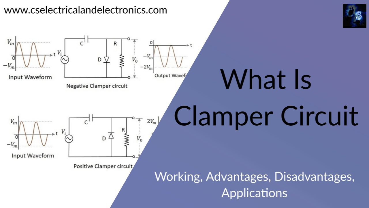
What Is Clamper Circuit
A clamper is a network consisting of diodes, resistors, and capacitors. Without changing the appearance of the applied signal, these diodes, resistors, and capacitors shift waveform to a different dc level. In this clamper circuit, an additional battery is also used if required. This clamper circuit can also be used to reinsert or restore the dc component into a waveform that has been lost after passing through the processing network such as an amplifier. Therefore clamper is also known as DC reinserted or DC restorer.
It is a circuit in which a DC level is added to the AC signal. By using this clamper circuit, the positive and negative peaks of signals can be adjusted. So as the dc level gets shifted in this clamper circuit, hence it is also called a level shifter. The time constant of charge and discharge of the capacitor will determine the output of the clamper circuit.
In this clamper circuit, the upward or downward vertical shifts take place in the output waveform with respect to the input signal. The capacitors and load resistors used in the clamper circuit affect the waveform so that the discharging time of the capacitor should be large enough. When capacitor coupled is used as a capacitor block, the dc component present in the input will be rejected. So, when dc supply needs to be restored, the clamping circuit is used in that situation.
Types Of Clamper Circuit
- Positive Clamper
- Negative Clamper
Positive Clamper
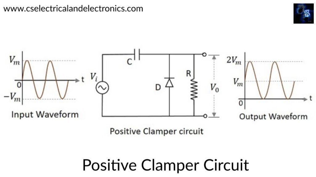
Generally, a clamper circuit restores the DC level. When in a negative half cycle the peak of a signal is raised above zero, then that signal is said to be positively clamped. Same as the clamper circuit, the positive clamp consists of a diode, resistor, and a capacitor but there is a difference in functioning i.e it shifts the output signal to the positive portion of the input signals so-called positively clamped.
When the input is given initially, the diode is reverse biased and the capacitor is not yet charged. At this point in time, the output is not considered. At the peak value of the negative half cycle, the capacitor gets charged with the help of negative on one of the plates and positive on the other. Then the capacitor is charged to its peak value so that the diode becomes forward biased and conducts heavily.
During the next positive half cycle, as the diode gets reverse biased and gets open-circuited and the capacitor is charged to positive Vm. Then at this moment, the output circuit will be the combination of both input signal and positive peak value Vm.
Vo = Vi + Vm
Hence from the above figure, the signal is positively clamped. According to the changes in the input the output signal changes, but according to the charge on the capacitor, the level gets shifted and adds to the input voltage.
Considering the RC time constant is very large than the time period, during the positive half cycle it will not be able to charge to the peak value and the output will follow the input signal. The diode will act as a short circuit and effectively the resistor RL will get short-circuited.
Negative clamper
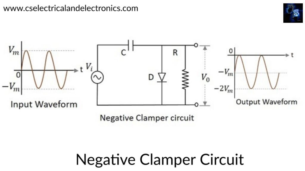
A negative clamper circuit is one that consists of a diode, a resistor, and a capacitor, and these components shift the output signal to the negative portion of the input signal. The above diagram explains the construction of a negative clamper circuit.
During the positive half cycle of this circuit, the capacitor starts getting charged to its peak value Vm. The diode gets forward biased and conducts. During the negative half cycle, the diode experiences reverse biased and get open-circuited. At this moment the output of the circuit will be,
V0=Vi+VmV0=Vi+Vm
Considering the ideal diode, it can be represented as a short circuit and the resistor will also get short-circuited. During the positive half cycle, the output voltage will be equal to zero and the polarity of the input voltage will get reversed.
Advantages of clamper circuit
01. Clampers give more reliable protection of the IGBTs than a soft turn-off circuit.
02. Clampers can remove the distortions frequently and identify the polarity.
Disadvantages of clamper circuit
01. The output waveform of the circuit is similar to the negative clamper output waveform.
Applications of clamper circuit
01. Clampers are used to clamp the waveforms to a fixed DC potential. So the campers are also called direct current restorers.
02. Clampers are used for the protection of the amplifiers from large arrangement signals.
03. Clampers are used for removing the distortions in the circuit.
04. Clampers are used as voltage doubters or voltage multipliers.
05. Clampers can also be found in storage counters, analog frequency meters, capacitance meters, dividers, and stair-case waveform generators.
06. Used for improving the overdrive recovery time.
I hope this article may help you all a lot. Thank you for reading.
Also, read:
- 10 Free ADAS Projects With Source Code And Documentation – Learn & Build Today
- 100 + Electrical Engineering Projects For Students, Engineers
- 100+ Indian Startups & What They Are Building
- 1000+ Automotive Interview Questions With Answers
- 1000+ Electronics Projects For Engineers, Diploma, MTech Students
- 1000+ MATLAB Simulink Projects For MTech, Engineering Students
- 2000+ Embedded Systems Interview Question Bank
- 2026 Hackathons That Can Change Your Tech Career Forever