Hello guys, welcome back to our blog. Here in this article, we will discuss what is interline power flow controller (IPFC) is, the purpose of IPFC, the working of interline power flow controller, and its applications.
If you have any electrical, electronics, and computer science doubts, then ask questions. You can also catch me on Instagram – CS Electrical & Electronics.
Also, read:
- Top 10 Electric Scooters In India, Best EV Scooties In 2022
- Top 12 Electrical Switch Manufacturing Companies In The World
- Difference Between 16-bit, 32-bit, And 64-bit Microcontrollers
What Is Interline Power Flow Controller (IPFC)
Interline Power Flow Controllers are an advancement of the Unified Power Flow Controllers (UPFC). Instead of power flow control, for a single line IPFC can control multiple transmission lines. Reactive power and Active power exchange between the over two lines are possible using IPFC. IPFCs are Voltage Source converters (VSCs) based on FACTS devices that provide series compensation to the line connected. For example, two voltage source converters can provide reactive and active power compensation to the series connected line.
Purpose of Interline Power Flow Controller (IPFC)
Interline Power Flow Controllers is a compensating system provided for transient interruptions in multiple lines. The capacity of the IPFC can control power flow for a sub-network system. IPFC injects voltage of controllable magnitude and a phase angle at a standard frequency for series compensation of the connected line. The two VSCs in an IPFC provide compensating voltage and current injection for the imperfections in the series connected line.
The DC link connecting two VSCs can efficiently transfer reactive and real power between VSCs. When overloading the burden, IFSC helps in real power exchange from overloaded lines to the compensating lines. The lines requiring actual power gets benefitted from underused lines. Instability causes detrimental fall or rise of bus voltages.
The fundamental problem in the power system is the voltage drop caused by insufficient real and reactive power compensations. This leads to system reliability issues and IPFC serves as a brilliant solution with voltage injecting capability. Synchronous machines in power systems often have rotor angle instability because of increasing angular swings.
We can sort this out with the help of IPFC through multiple-line power flow control via the DC link. IPFCs also find their purpose in improving the small signal stability of the power system by adding supplementary signals for damping low-frequency oscillations. They also increase system transient stability by returning the unstable system to a stable equilibrium point and, in turn, limiting the corrective actions for large disturbances in the synchronous machines.
Working on Interline Power Flow Controller (IPFC)
Each series transformer connected to the compensating lines connects the AC side of the Voltage Source Converters (VSCs) and the DC sides of the VSCs are coupled through a DC capacitor. The DC capacitor serves as the DC terminal where the DC link voltages are monitored for the exchange of compensating powers between the VSCs. For example, let us consider just two VSCs connected with the lines.
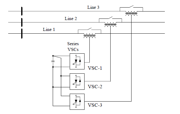
The two voltage source converters produce pure sinusoidal voltages (VCO1 & VCO2 ). VCO1 represents the system 1 exchange of the actual power and reactive power (Pse1 & Qse1) between VSC-1 and the line.
To analyze in detail the VCO1 is decomposed into d and q components. Vco1d component affects the actual power of the lines and the Vco1q component affects the reactive power of the lines. When the Qse1 is directly supplied from the VSC-1 of the connected line, the Pse1 imposed by the VSC-1 represents a real power demand on the DC terminal. The DC link voltage imbalances and takes support from the VSC-2 connected.
Thus the freedom of degrees is limited for the secondary VSC (VSC-2) and it has to fulfill the demand from VSC-1. Therefore, the main job of VSC-2 is to regulate the DC link voltage and compensate for the real power demand and should limit the constraints imposed.
Pse1 + Pse2 = 0 (constraint)
The steady-state equation for an n number of converters can be given below equation,
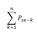
The VSC-1 has two independently controlled variables (VCO 1& θco1) while the VSC-2 has one controlled variable VCO2q . From the operation of IPFC, one can understand that any of the converters within the IPFC system can exchange actual power with the other and also independently control reactive power for series compensation.
Thus, the Interline Power Flow Controllers (IPFC) of each system helps achieve power optimization by satisfying the power flow constraints. We can design the IPFCs as one or more static synchronous series compensators or even two UPFCs together in series.
Operational constraints
During the effective implementation of IPFCs, some operational constraints account for a power system. The constraints are as follows:
- Operating limits of bus voltages before and after series compensation.
- Ratings of series and shunt VSCs to enhance the controlled region of operation.
- Transfer limit of actual power via DC link
- The magnitude of voltages provided by the VSCs
- The capacity of compensation assisting converters.
- Limitations of the secondary compensating shunt converter ratings.
- Protection of power electronics semiconductor devices.
- Thermal and stress constraints of semiconductor devices.
- Optimized switching losses in Interline Power Flow Controller (IPFC).
Advantages of IPFC
- Essentially, IPFC can protect power system equipment from overloading and under-loading of transmission lines.
- Enhance protection by minimizing contactor wear and tear.
- Reduces the degree of field failures.
- In case of harmonic distortion such as voltage and current distortion, it can switch off the system through any of the Voltage Source Converters.
- On the occurrence of faults, VSCs shuts off capacitor banks.
- Avoid PF penalties through proper reactive compensations.
- Faulty operation through manual control is minimized, which also prevents switching devices manually.
- On any system, failure monitoring and signaling are enhanced and clear alarm.
Disadvantages of IPFC
- On series voltage injection, the IPFCs can make the voltages in nonstiff buses cross their bus voltage operating limits. This causes proscribed overvoltages and damages the system equipment.
- The transmission angle increase or decrease for the compensating line affects the line current in the uncompensated line. Hence, it has a negative impact on the uncompensated lines.
- Since the VSCs used in the system almost have the same capacity, the control area of the compensating converter remains limited. For instance, the converter VSC-2 cannot accomplish compensating for both the lines.
- Imposes limitation in the operative series compensation voltage because of the technical limits.
Applications of IPFC
- Transient Stability improvement.
- Employed in Power Transmission system.
- Low-frequency oscillations damping.
- Control power oscillation dampings.
- Improves voltage stability.
- Reactive and real power flow control.
- Enhanced for rotor angle stability.
- Equalize both real and reactive power.
This was about “What Is Interline Power Flow Controller (IPFC)“. I hope this article may help you all a lot. Thank you for reading.
Also, read:
- “Mother of All Deals”: How The EU–India Free Trade Agreement Can Reshape India’s Economic Future
- 10 Free ADAS Projects With Source Code And Documentation – Learn & Build Today
- 10 Tips To Maintain Battery For Long Life, Battery Maintainance
- 10 Tips To Save Electricity Bills, Save Money By Saving Electricity
- 100 (AI) Artificial Intelligence Applications In The Automotive Industry
- 100 + Electrical Engineering Projects For Students, Engineers
- 100+ C Programming Projects With Source Code, Coding Projects Ideas
- 100+ Indian Startups & What They Are Building