Hello guys, welcome back to our blog. Here in this article, we will discuss what is unified power flow controller or UPFC is, the purpose of UPFC, its working, its advantages, disadvantages, and its applications.
If you have any electrical, electronics, and computer science doubts, then ask questions. You can also catch me on Instagram – CS Electrical & Electronics.
Also, read:
- What Is Interline Power Flow Controller (IPFC), Purpose, Applications
- Difference Between Kalman, Extended Kalman, Unscented Kalman Filter
- Top 13 Websites For Research Papers For Engineers, MTech Students
What Is Unified Power Flow Controller (UPFC)
Unified Power Flow Controller (UPFC) is a Flexible AC Transmission System (FACTS) based real and reactive power compensating device. It is a flexible device compared to three-phase controlled bridges.
A UPFC is a combination of series and shunts connected Voltage source Converters connected back to back in other means we can also call it a combination of Static Compensators (STATCOM) and Static Series Synchronous Compensators (SSSC) linked via DC bus ( DC link voltage). It provides active and reactive power control for a transmission line.
Purpose of Unified Power Flow Controller
UPFC FACTS devices boost power flow regulation through series and shunt connected back-to-back with each other. A DC capacitor bank between the converter can store energy for compensation. The main purpose of UPFC are listed here:
- Control of line reactive and active power.
- Enhances Power system capacity.
- Limits transitory disturbances.
- Upgrade synchronous rotor angle stability.
- Strengthens system against low-frequency damping oscillations.
- Protects the transmission line during any faults or disturbances, i.e., UPFC disconnects during any fault.
- Subdue power system oscillations.
Working of Unified Power Flow controller (UPFC)
UPFC consists of a shunt-connected voltage source converter VSC-1 coupled with the transmission line via a coupling transformer and a series connected voltage source converter VSC-2 connected via a series transformer. Both converters are connected back to back and coupled through DC capacitor banks.

The shunt and series connected converters provide active and reactive power compensation for the connected transmission line. The series connected VSC-1 exchange both reactive and real power by controlling the injected voltage between Vpq– Vpq,max, and phase angle between 0-3600.
While the shunt converter VSC-2 compensates for the real power demand by supplying from the transmission line to the VSC-1. VSC-2 also maintains constant voltage at the DC terminals. The DC capacitor banks help for the absorption and generation of actual power through energy storage. Overall the net real power drawn from the power system equalizes with the losses imposed in the two converters.
Operational constraints of UPFC
- The magnitude of the series voltage injected into the transmission line.
- Compensating line current constraints.
- Rating of shunt connected converter.
- Power transfer limits of the UPFC to the transmission line
- Actual power transfer capacity between series and shunt-connected converters.
Power Flow control functions of Unified Power Flow Controller (UPFC)
Functions that can be performed with the UPFC controller are listed below:
- Voltage injection for the transmission line.
- Regulation of terminal voltages.
- Line impedance regulation.
- Phase angle regulation.
Modes of operation of UPFC
Unified power flow controllers can operate in different modes of operation depending upon the power flow control function. Some of them are listed here:
- STATCOM control mode
- Control of Reactive power
- Automatic voltage control
- SSC control mode
- Direct voltage injection.
- Regulation of bus voltage and phase angle
- Compensation for Line impedance
- Automatic power flow control.
Operating modes of UPFC
The operating modes of the UPFC mainly depend on the direct component and the quadrature component of the transmission line current with respect to the voltage. The direct component or the real component may either be in phase or opposite to the line voltages, while the reactive or quadrature component is in quadrature.
The direct component specifies the real power demands either to absorb or generate real power. In contrast, the quadrature component specifies reactive power absorption or generation based on the capacity of the inverter.
STATCOM control mode
I. Control of reactive power
With the help of a dc voltage reference and VAR control reference, the desired shunt current request is fulfilled with the help of a shunt converter gating control. This provides the required current compensation.
II. Automatic Voltage Control
The shunt-connected VSC-2 regulates the transmission line voltage with a reference voltage. The sending end of the transmission lines feedbacks voltages via the coupling transformer to control the voltages. The power flow control provided through a series connected VSC-1 adjusts the voltage magnitude and provides phase angle control.
III. Direct Voltage Injection
The series-connected converter directly references voltage magnitude and phase angle and provides direct voltage injection.
IV. Regulation of bus voltage and phase angle regulation
The difference between the sending end and receiving end voltages and phase angles are directly referenced to the input of the series converter VSC-1.
V. Compensation of Line Impedance
A series impedance value inserted along with the line impedance is referenced to the series converter VSC-1.
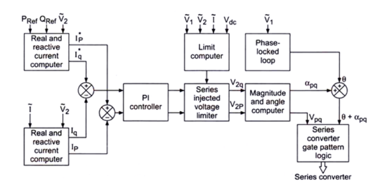
VI. Automatic Power Flow Control
The series converter VSC-1 takes actual power (P) and reactive power (Q) reference values. These references are compared with the actual P and Q and the resulting error values when given to PI regulator to generate corresponding Vd and Vq components.
These components are synthesized by VSC-1 voltage regulation to compensate for the actual and reactive power demands. Vd corresponds to the actual power regulation and Vq corresponds to the reactive power generation.
Advantages of Unified Power Flow Controller (UPFC)
- Flexibility to control transmission line parameters such as voltage, phase angle, line impedance, and active and reactive power.
- Protects transmission line against faults and disconnects automatically.
- Helps minimize generation costs.
- Enhance loading of the power system.
- Minimizes power losses.
- Improves transmission capability.
- Strengthens the system against voltage instability.
- Damps power swings and increases power angle stability.
Disadvantages of Unified Power Flow Controller (UPFC)
- Requires a robust structure.
- The capacitor banks affect the reliability of the controller.
- Only compensation is provided to the single transmission line.
- There are no guidelines to provide suitable UPFC parameters.
- UPFC works on after-power flow results and there is no way to check whether they operate within limits.
- Target power flow can be achieved only through trial and error.
Applications of Unified Power Flow Controller (UPFC)
- It can be used to damp power oscillations.
- Improve performance of wind energy conversion system through controlling dc link faults.
- Suitable to enhance dynamic power quality.
- Real-time applications to control voltage, current, and line impedances.
- UPFC provides contingency management.
- Sharing of spinning reserves among the connected lines based on transfer and thermal capacity.
This was about “What Is Unified Power Flow Controller (UPFC)“. I hope this article may help you all a lot. Thank you for reading.
Also, read:
- 10 Tips To Maintain Battery For Long Life, Battery Maintainance
- 10 Tips To Save Electricity Bills, Save Money By Saving Electricity
- 100 (AI) Artificial Intelligence Applications In The Automotive Industry
- 100 + Electrical Engineering Projects For Students, Engineers
- 100+ Indian Startups & What They Are Building
- 1000+ Automotive Interview Questions With Answers
- 1000+ MATLAB Simulink Projects For MTech, Engineering Students
- 2024 Is About To End, Let’s Recall Electric Vehicles Launched In 2024