Hello guys, welcome back to our blog. In this article, we will discuss the types of automotive sensors and actuators used in electric vehicles, and sensors used in the latest electric cars, and we will give a short description of each sensor and actuator.
If you have any electrical, electronics, and computer science doubts, then ask questions. You can also catch me on Instagram – CS Electrical & Electronics.
Also, read:
- What Is CMOS, Complementary Metal Oxide Semiconductor, Diagram.
- What Is Modulation, Demodulation, Types, Need For Modulation.
- Roadmap To Become A Embedded Engineer, Jobs, Roles, Responsibilities.
Types Of Automotive Sensors and Actuators
There are various kinds of sensors used in automotive or electric vehicles to read the real-time signals and take necessary actions to manage in-vehicle functions such as ignition time, ABS, speed control, etc. The types of automotive sensors and actuators are:
- 01. Engine speed sensor
- 02. Wheel speed sensor
- 03. Vehicle speed sensor
- 04. Throttle position sensor
- 05. Temperature sensor
- 06. Mass airflow (MAF) rate sensor
- 07. Exhaust gas oxygen concentration sensor
- 08. Crankshaft angular position/RPM sensor
- 09. Manifold Absolute Pressure (MAP) sensor
- 10. Accelerometer (knock sensors)
These are the commonly used sensors. There may be other sensors based on the automotive application. All these sensors are associated with the power trains.
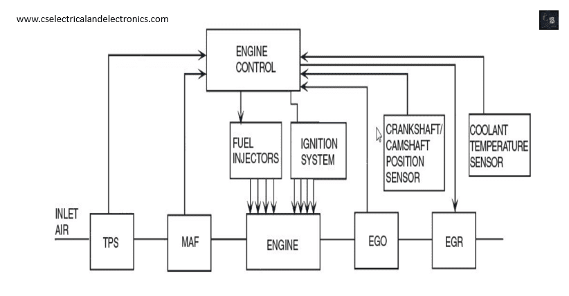
General Block Diagram Types Of Automotive Sensors and Actuators
01. Engine Speed Sensor
An engine speed sensor is needed to provide input for the electronic controller for several functions. The reluctance sensor can be used to measure engine speed. The four tabs will pass through the sensing coil once for each crankshaft revolution.
We count the pulses of voltage from the sensing coil in one minute and divide by four, we will know the engine speed in revolutions per minute (RPM). An electronic circuit is used to start and stop the counter circuit. The counter can be used to count the number of pulses through a special signal processing circuit.
02. Wheel speed sensor
Used in ABS, Odometer. Contactless – Magnetic or optical method. Magnetic method – Hall effect. The sensor provides square wave output whose frequency is proportional to the wheel speed.
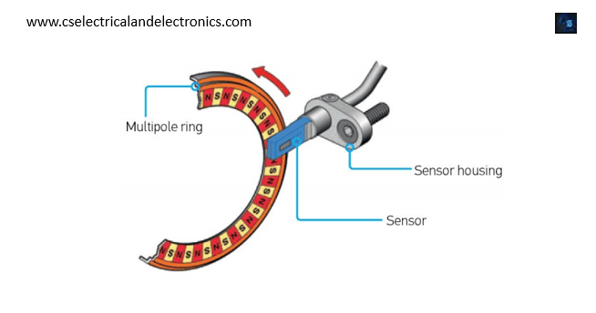
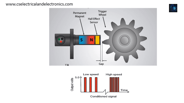
Wheel-speed sensor using Hall technology incorporates the Hall-sensing element, signal amplifier, and signal processing all on a single chip. It consists of a transistor whose base is excited by the magnetic effect. The circuit is exposed to the changing magnetic field of the rotating encoder, which is either a multipole or a steel wheel. In the case of a steel wheel application, a magnet placed inside the sensor is needed. Changing the magnetic field around the Hall element induces an alternating voltage across the same.
The alternating voltage is proportional to the changing magnetic field. The sinusoidal voltage is processed by the circuit into an alternating digital output signal. The frequency of the current pulses is directly proportional to the wheel speed. Detection of very low speed nearly up to stand-still (0.1km/h) is possible.
03. Vehicle Speed Sensor
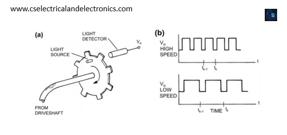
The ECM (Engine control module) uses this information to modify engine functions such as ignition timing, air/fuel ratio, transmission shift points, and to initiate diagnostic routines. Used in ABS (wheel speed sensor), speedometer, and cruise control system. The Vehicle Speed sensor or VSS measures transmission/transaxle output. The Vehicle Speed sensor is typically located at the transmission or transaxle. The speed sensor can be implemented magnetically or optically.
04. Throttle Position Sensor
A variable that must be measured for electronic engine control is the throttle plate angular position. The throttle plate is linked mechanically to the accelerator pedal. The throttle plate restricts the airflow into the intake manifold When the driver depresses the accelerator pedal, this linkage causes the throttle plate angle to increase, allowing more air to enter the engine and thereby increasing engine power. Most throttle angle sensors are essentially potentiometers.
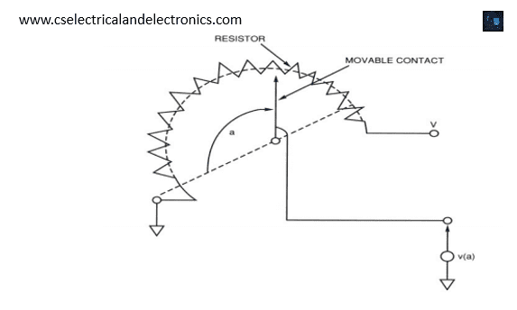
This potentiometer can be used to measure any angular rotation, in particular the throttle angle. The only disadvantage to the potentiometer for automotive applications is its analog output. For digital engine control, the voltage v(a) must be converted to digital format using an analog-to-digital converter.
05. Temperature Sensor
Temperature is an important parameter throughout the automotive system. In an electronic fuel control system, it is vital to know the temperature of the coolant, the temperature of the inlet air, and the temperature of the exhaust gas oxygen sensor.
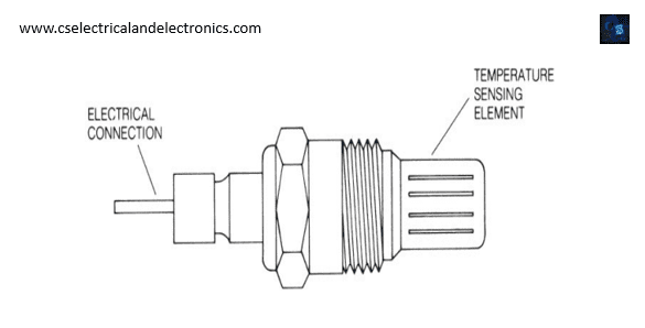
Consists of a thermistor mounted in a housing that is designed to be inserted into the coolant stream. This housing is typically threaded with pipe threads that seal the assembly against coolant leakage. A thermistor is made of semiconductor material whose resistance varies inversely with temperature. For example, at –40˚C a typical coolant sensor has a resistance of 100,000 ohms. The resistance decreases to about 70,000 ohms at 130˚C.
06. Air Flow Rate Sensor
The correct operation of an electronically controlled engine requires a measurement of the mass flow rate of air (Rm) into the engine. This requires a sensor that can sense the airflow rate into the intake manifold of the engine. The sensor is normally mounted as part of the air cleaner assembly.
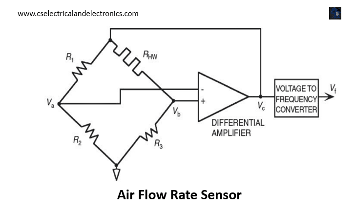
Rhw is a heated filament resistor. The resistance of the filament changes as the temperature of the filament changes. This is used in Wheatstone’s network. The output of this n/w is given to a differential amplifier. The resulting analog output is fed to the V/F converter.
The film element is electrically heated to a constant temperature above that of the inlet air. As air flows across the hot film, heat is carried away from the film by the moving air. The amount of heat carried away varies in proportion to the mass flow rate of the air. The heat lost by the film to the air tends to cause the resistance of the film to vary, which unbalances the bridge circuit, thereby producing an input voltage to the amplifier. This voltage is given to a V/F converter – a variable-frequency oscillator whose frequency is proportional to the input voltage.
07. Exhaust Gas Oxygen Concentration Sensor
Feedback control for fuel delivery is based on maintaining the air/fuel ratio at stoichiometry (i.e., 14.7:1 – torque reaches a maximum for this ratio). In order to burn completely 1 kg of fuel, we need 14.7 kg of air. The amount of oxygen in the exhaust gas is used as an indirect measurement of the air/fuel ratio. Also known as lambda sensor.
Equivalence ratio λ = (air/fuel)/(air/fuel at stoichiometry)
- The mixture at stoichiometry (ideal) when lambda=1
- The mixture is lean (lean fuel, more air) if lambda > 1
- The mixture is rich (more fuel, lean air) if lambda < 1
Two types of sensors: –
- zirconium dioxide (ZrO2 ) – titanium dioxide (TiO2 ).
- zirconium dioxide is the most commonly used.
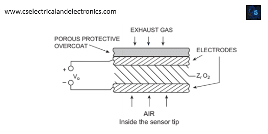
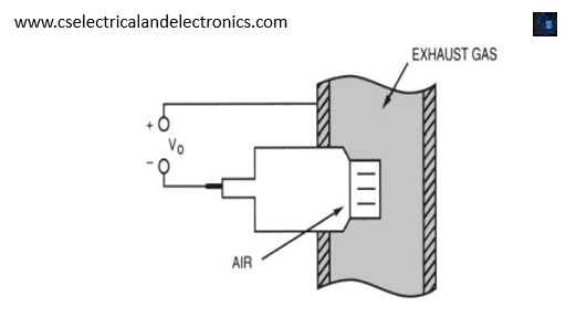
The EGO sensor consists of a thimble-shaped section of ZrO2 with thin platinum electrodes on the inside and outside of the ZrO2. The inside electrode is exposed to air, and the outside electrode is exposed to exhaust gas through a porous protective overcoat. Oxygen ions have two excess electrons and each electron has a negative charge; thus, oxygen ions are negatively charged.
The ZrO2 has a tendency to attract oxygen ions, which accumulate on the ZrO2 surface just inside the platinum electrodes. The platinum plate on the air reference side (inside) of the ZrO2 is exposed to a much higher concentration of oxygen ions than the exhaust gas side.
The air reference side becomes electrically more negative than the exhaust gas side. Therefore, an electric field exists across the ZrO2 material, and a voltage, Vo, results. The polarity of this voltage is positive on the exhaust gas side and negative on the air reference side of the ZrO2. The magnitude of this voltage depends on the concentration of oxygen in the exhaust gas and on the sensor temperature.
The quantity of oxygen in the exhaust gas is represented by the oxygen partial pressure. (proportion of the total exhaust gas pressure/atmospheric pressure that is due to the quantity of oxygen.)
• EGO partial pressure
– for rich mixture is 10–16 to 10–32 of atmospheric pressure.
– for lean mixture is ~10–2 of atmospheric pressure
Consequently, for a rich mixture, there is a relatively low oxygen concentration in the exhaust and a higher EGO sensor output. For a lean mixture, the exhaust gas oxygen concentration is relatively high resulting in a relatively low EGO sensor output. For a fully warmed EGO sensor, the output voltage is about 1 volt for a rich mixture and about .1 volt for a lean mixture.
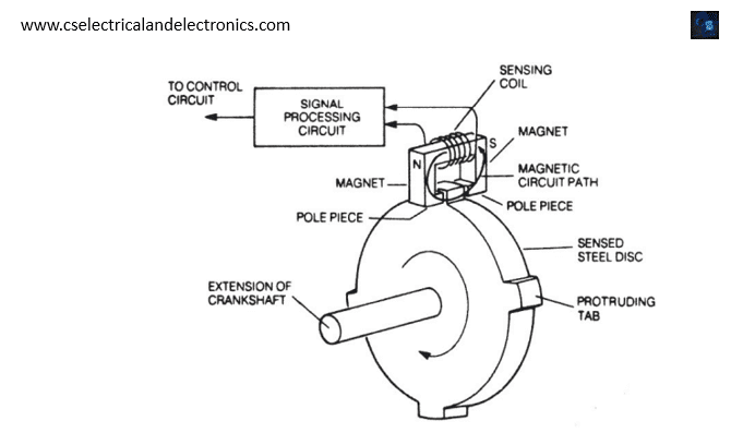
08. Crankshaft Angular Position/RPM Sensor
Crankshaft position measured directly using magnetic phenomena. This sensor consists of a permanent magnet with a coil of wire wound around it. A steel disk that is mounted on the crankshaft (usually in front of the engine) has tabs that pass between the pole pieces of this magnet. This sensor is of the magnetic reluctance type and is based on the concept of a magnetic circuit. Reluctance – opposition to magnetic flux.
A magnetic circuit is a closed path through a magnetic material. The magnetic circuit here is the closed path through the magnet material and across the gap between the pole pieces. When a tab on the steel disk passes through the gap, the flow of the magnetic flux changes significantly. The reluctance of a magnetic circuit is inversely proportional to the magnetic permeability of the material along the path.
The magnetic permeability of steel is a few thousand times larger than air; therefore, the reluctance of steel is much lower than air. The steel has a lower reluctance than air, and the “flow” of magnetic flux increases to a relatively large value. This rate of change of flux induces a voltage across the coil. A peak in voltage indicates a tab crossing the pole piece as shown.
09. Manifold Absolute Pressure (MAP) Sensor
The MAP sensor measures the absolute pressure inside the intake manifold of the engine. MAP Sensor- Silicon diaphragm diffused strain gauge.
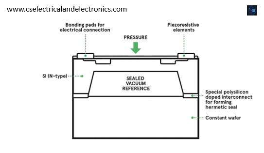
Piezoresistivity occurs in certain semiconductors so that the actual resistivity (a property of the material) changes in proportion to the strain (fractional change in length). The strain induced in each resistor is proportional to the diaphragm deflection, which, in turn, is proportional to the pressure on the outside surface of the diaphragm. This pressure is the manifold pressure. Wheatstone bridge is used for measurement of strain.
10. Accelerometer (knock sensors)
Another sensor having application in closed-loop engine control is the so-called knock sensor. This sensor is employed in closed-loop ignition timing to prevent undesirable knock. Knock can be described generally as a rapid rise in cylinder pressure during combustion. It occurs most commonly with high manifold pressure and excessive spark advance. Knocking has to be detected and prevented so as to
minimize engine and valve damage.
One way of controlling knocking is to sense when knocking begins and then retard the ignition until the knocking stops. A knock sensor using magnetostriction to sense or detect knock. Other sensors use piezoelectric crystals or the piezoresistance of a doped silicon semiconductor. Magnetostriction is a phenomenon whereby the magnetic properties (magnetic susceptibility or permeability) of a ferromagnetic material change depending on stress.
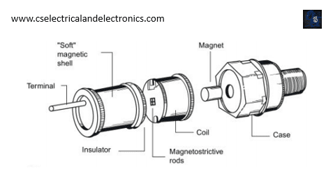
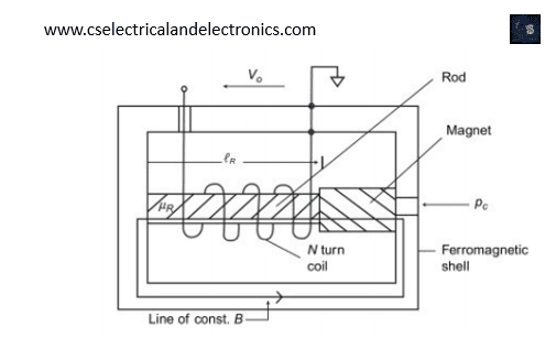
The forces associated with knock cylinder pressure are transmitted through the mounting frame to the magnetostrictive rods. When sensing knock, the magnetostrictive rods, which are in a magnetic field, change the flux field in the coil due to knock-induced forces. This change in flux produces a voltage change in the coil. This voltage is used to sense excessive knock. Possible measures to overcome knocking are retarding the timing, adding fuel, reducing boost pressure, etc. The frequency of knock is specific and depends on the bore (piston) diameter of the engine. DSPs improve the SNR (signal-to-noise ratio) to detect knock.
This was about “Types Of Automotive Sensors and Actuators“. I hope this article “Types Of Automotive Sensors and Actuators” may help you all a lot. Thank you for reading.
Also, read:
- 10 Free ADAS Projects With Source Code And Documentation – Learn & Build Today
- 100 + Electrical Engineering Projects For Students, Engineers
- 100+ Indian Startups & What They Are Building
- 1000+ Automotive Interview Questions With Answers
- 1000+ Electronics Projects For Engineers, Diploma, MTech Students
- 1000+ MATLAB Simulink Projects For MTech, Engineering Students
- 2026 Hackathons That Can Change Your Tech Career Forever
- 50 Advanced Level Interview Questions On CAPL Scripting