Hello guys, welcome back to my blog. In this article, I will discuss what is heart beat sensor, working of heart beat sensor, applications means where it is used, circuit diagram, interfacing of heart beat sensor with Arduino, etc.
If you have any doubts related to electrical, electronics, and computer science, then ask question. You can also catch me @ Instagram – Chetan Shidling.
Also, read:
- What Is Rain Sensor, Working, Rain Sensor With Arduino, Circuit Diagram.
- Difference Between Step And Touch Potential, Why It Occurs.
- Top 10 Latest Technologies In Electrical And Electronics Engineering.
What Is Heart Beat Sensor
It is used to measure the heart rate i.e., how many times the heart beats (speed). Generally, body temperature is measured with a thermometer, and blood pressure is measured with Sphygmomanometer. Nowadays, heartbeat sensors are used in smartwatches, smartphones. Heartbeat rate can be monitored in two ways. By checking the pulse and by using a heartbeat sensor.
This sensor can be monitored using Arduino. Most of the athletes, patients are worried about their heartbeat. This monitoring is to determine the condition of the heart. Checking heartbeat using a heartbeat sensor is the updated one.

It is easier to monitor the heart rate by using this sensor. The main principle involved in a heartbeat sensor is Photoplethysmograph. The change in volume of blood in an organ is measured by the change in the intensity of the light which is passing through the respective organ. IR LED is the source of light used in the heartbeat sensor. An LDR, Photodiode, and phototransistor are the detectors used. The sensor can be attached to the finger or ear.
With the light source, the transmissive sensor is arranged. In this sensor, the light source and the detector are facing each other and the finger of the person must be placed in between the transmitter and receiver. The reflective sensor has the light source and detector are adjacent to each other and the finger must be placed in front of the sensor.
This sensor is designed to give the digital output of the heartbeat when the finger of a person is placed on it. While the heartbeat detector is in working condition, the beat LED glows with a heartbeat. The digital output connected to the microcontroller measures the beats per minute rate.
Working Of Heart Beat Sensor
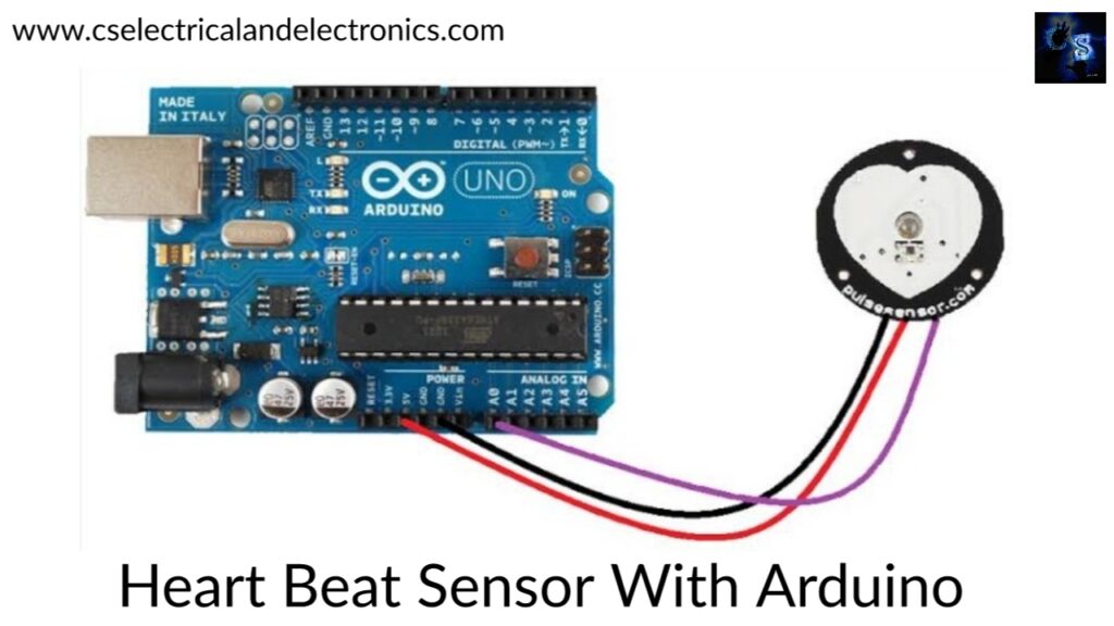
A heartbeat sensor consists of a control circuit and a sensor. The sensor part consists of an IR LED and a photodiode or phototransistor placed in a clip. The control circuit consists of an Op-Amp IC and other components for connecting the signal to a microcontroller. The finger-type heartbeat sensor works by detecting the pulses. The heartbeat sensor is placed on the finger in which the heartbeat will alter the amount of blood. The light from the IR LED passes through the finger and the sensor detects the signal using the photodiode or phototransistor, this can be varied. The output of the photodiode or phototransistor is given to the non-inverting input of the first op-amp through a capacitor. This capacitor blocks the DC components of the signal due to the absence of capacitance in DC.
The output of the first op-amp is connected as one of the inputs to the second op-amp, this will act as a comparator. The triggering of the transistor is done by the output of the second op-amp, the obtained signal is given to an Arduino. The op-amp used in this circuit is LM358. LED and transistor are connected to each other, an LED will blink when the pulse is detected.
Components Required
- 330-ohm resistor
- Heartbeat sensor module with the probe
- Breadboard
- Arduino UNO
- 10k ohms potentiometer
- LCD display
- Connecting wires
This is a simple circuit that displays the heartbeat reading in beats per minute. Connect LCD display to the Arduino UNO. The 4 pins of the LCD display are connected to D4, D5, D6, D7. A 10-kilo ohm potentiometer is connected to pin 3 of the LCD. Now, connect the output of the heartbeat sensor module to the analog input pin of the Arduino.
Firstly, the code is uploaded to the Arduino and then power on the circuit. The Arduino reads the code and asks to place the finger in the sensor and press the switch. Place any finger except the thumb finger in the sensor and press the switch. Based on the heart rate the sensor collects the data, Arduino senses that and calculates the heart rate, and displays the heartbeat rate in beats per minute (bpm).
Do not shake the wire and sit down relaxedly while the sensor is collecting the data. If the wire gets shaken it might result in faulty or inaccurate values.
Applications Of Heart Beat Sensor
- To calculate heart rate of a person.
- Smart watches and smart gadgets.
- Medical
I hope this article may help you all a lot. Thank you for reading.
Also, read:
- 10 Free ADAS Projects With Source Code And Documentation – Learn & Build Today
- 100 + Electrical Engineering Projects For Students, Engineers
- 100+ Indian Startups & What They Are Building
- 1000+ Automotive Interview Questions With Answers
- 1000+ Electronics Projects For Engineers, Diploma, MTech Students
- 1000+ MATLAB Simulink Projects For MTech, Engineering Students
- 2026 Hackathons That Can Change Your Tech Career Forever
- 50 Advanced Level Interview Questions On CAPL Scripting